
I often capture time lapse image sequences and do astrophotography. In both applications, a trigger cable and a proper means of powering the camera are essential. Keep in mind, that a fully charged battery usually lasts for no more than 3 hours.
At the moment, the only way to power a Sony mirrorless camera for a whole night or several hours is a dummy battery attached to a power supply (be it a mains power supply or a 7.2V battery driven sollution). With the release of the new models recently, like the A7III or A6400, the camera may also be powered through USB charger during image acquisition. (It may still be possible, that the battery drains, but far far less.)
This is really good news, as a USB power bank will provide the juice to run a whole night or even longer! But there arises one new problem: The external trigger remotes use the same USB port as it is used for charging.
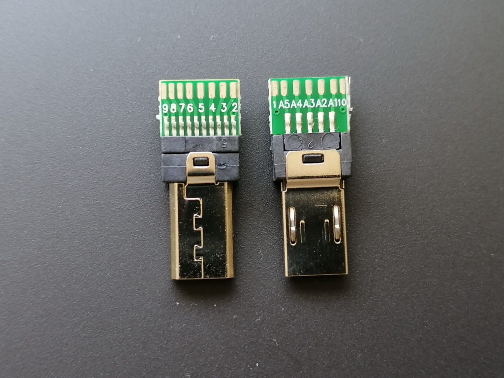
This is possible, as Sony has created the so called Multiport some time back for use with their video cameras. The Multiport is an extended Micro-USB port with a second row of contacts. These contacts provide access to some control as well as audio and video output.
I did some research and came across Multiport connectors with solder pads for all 15 pins. See the pinout in the images at the end of the post.
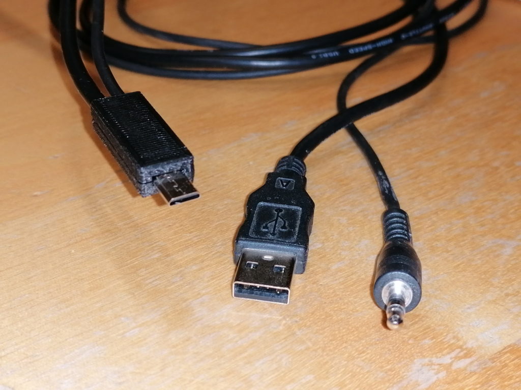
With such connectors I was able to tailor a dual cable adapter, to charge and trigger the camera at the same time! I took a USB cable with male type A connector and a headphone extender cable with male 3.5mm plug. I chose both cables around 1m in length. This should be long enough in most use cases, but not too long to reduce charging performance.
The 3.5mm plug fits some of my trigger devices. All the others have 2.5mm plugs, for which I have adapter calbes in use. Most computer timer remotes with interchangeable camera plug sold, have a 2.5mm female audio jack. See attached image for the typical pinout.
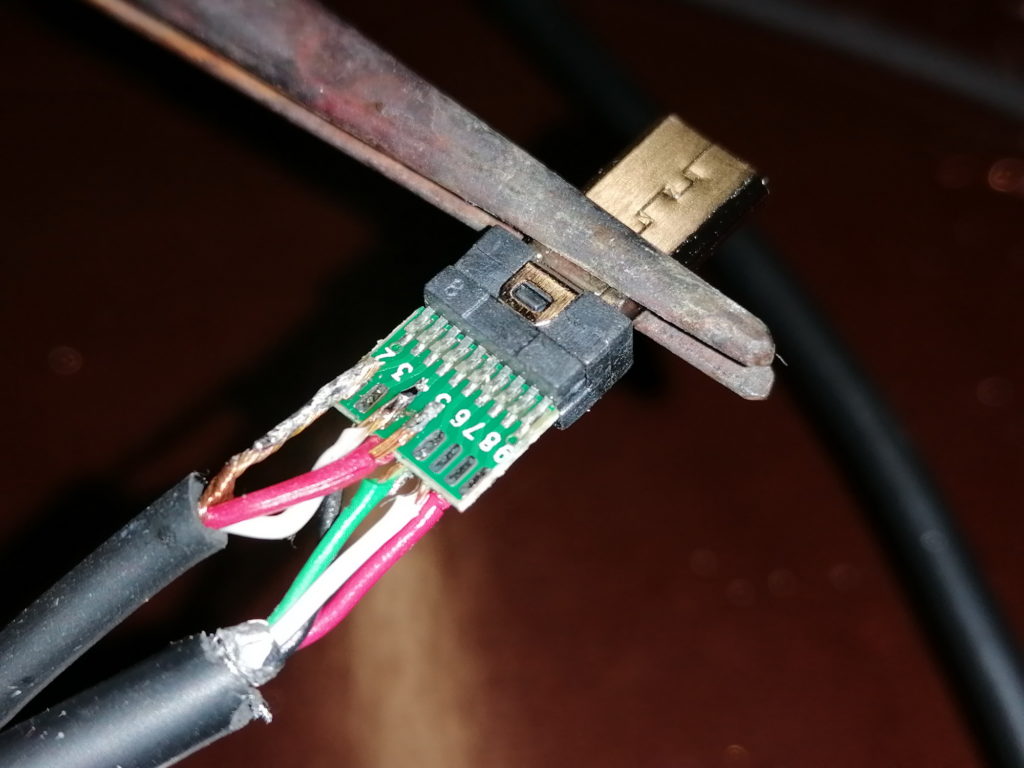
Soldering the two cables to the tiny solder pads requires a steady hand and experience in soldering. The USB as well as the audio cables have quite thin wires (AWG26 to AWG28, which equals to 0.12 mm² to 0.08 mm²), except the USB power wires (AWG22 or AWG24 in quick charge cables, which equals to 0.32 mm² and 0.20 mm²). The wires are rather stiff. Therefore, aligning the wires to the solder pads may be tricky. It gets especially tricky, if the wires are exposed from the outer isolation for less than a centimeter.
Advice: Always check the finished cable for shorts and proper contact with a multimeter!
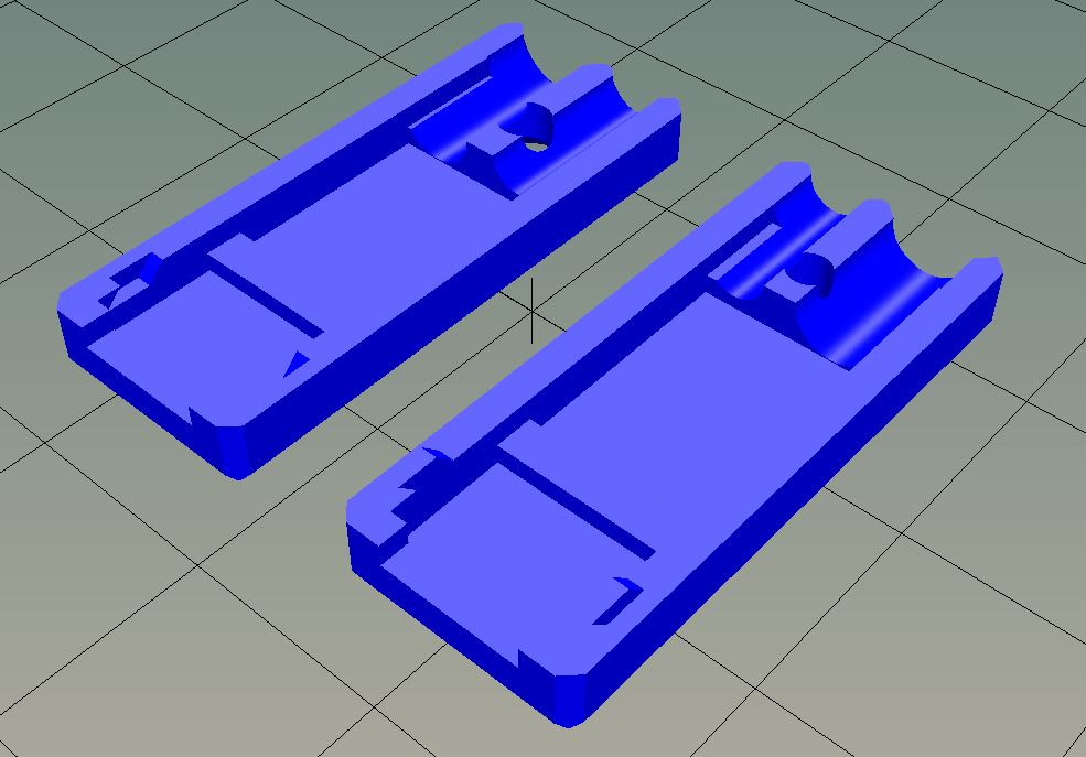
To reduce wear, which may lead to wires breaking off the solder pads, I designed a connector housing / case. The housing holds the adapter as well as the cables in place. Furthermore, this is the only proper way to handle the connector upon pluggin to / unpluggin from the camera.
The connector case is 3D printed. I share the STL file on Thingiverse here:
https://www.thingiverse.com/thing:4279366


Disclaimer:
This is a guide put together as reference for me. If you follow this description, you will do so on your own risk. I may not be held responsible for any damage or injury caused!
Hi MatP
I found your website while trying to make a shutter release cable for my a6600 that can also charge it. Thanks for the very useful guide and diagrams.
I have a question: have you attempted to use the 3.3V output from that port? Do you know anything about it?
Thanks
Frank
You might be interested in something I’m working on: https://github.com/frank26080115/OpenMV-Astrophotography-Gear
I would love to hear your feedback as you are also an engineer who does astrophotography.
Hi Frank!
I moved your comment from the About page to the “Combined charger and trigger cable…” page, as it refers to this page.
You are very welcome!
I did not yet have the need to harvest the 3.3V from the Multi-Port. So I have to dig in to the port specs. But as far as I remember, the 3.3V output is designed for low power applications.
So without further reading, my guess would be: an active microphone oder microcontroller – yes. A GPS unit – probably. An external HDMI display – definitely no.
MatP
PS: love your 7E tag line 😉
Hi Frank!
I went through several documents. I could not find a hint on maximum allowed power consumption on 3.3V LANC_DC line (the 3.3V output on Sony Multiport Interface).
The circuit diagrams and connectors of some LANC interfaces indicate, that the 3.3V line will not supply a lot of current. This is derived from:
1) a standard USB connector is designed for maximum currents of 500mA. The LANC_DC pin uses similar wire widths.
2) a 2.5mm stereo phone jack (TRS connector) is rated for maximum current of 500mA. The 2.5mm jack is one connector type used for LANC interfaces.
3) the LANC voltage in video cameras is provided by a microchip without voltage regulator / voltage driver chips. All (or almost all) other voltages within the cameras (as I have found in service manual schematics) are controlled by the same chip, though they are backed by regulators.
4) the majority of LANC interface hardware without their own power supply are simplistic switch devices for shutter, focus, zoom, … So they do not need a lot of hardware (apart from LANC communication)
5) one of the LANC to RS232 interface chips (ELM Electronics ELM624 https://www.elmelectronics.com/ic/elm624/) has a maximum current draw of 2.4mA. So it is a low power interface. Combined with a micro controller, these switch devices may run at a few mA – most likely far less than 20mA.
So, as long as I do not find the specifications of the LANC interface, I would rather use a separate power supply (battery, USB power bank, …) to drive any hardware drawing more than – probably – 50mA.
Hi MatP
I use sony HDR-PJ240E handy cam. There no external mic connector on the cam. But it have multi connector. How can I use multi connector use to external mic connectivity or any other idea?
Thank and regards
Manoj Soorya
.
Hi Manoj,
I went through some documentation of your camera model. Unfortunately for you, I could not find any possibility to connect an external microphone.
The Multi-Port connector has no Audio-In option. The audio lines are solely for audio out or remote shutter use. Sony cameras without dedicated microphone in connector may provide the Multi-Interface shoe (flash hot shoe) with microphone pins. But your camera model is not equipped with such hot shoe.
So, the only option I see would be to record audio on a separate device. Then combine the audio and video in your cutting software.
All the best!
MatP
Hi Matp, we are looking at doing a project where we have a vehicle on a turntable and when the turntable gets to a certain rotation a signal is sent to start the camera and video, then when the turntable has completed a 360-degree rotation it stops the camera and video. Next is possible we would like to send the captured images down the down the USB (using a twin port USB cable) to a computer for processing, is all that possible using the Sony Multiport Connector?
Cheers Joe
Hi Joe,
Your project sounds interesting!
Controlling the turntable is quite easy. Either you have a servo or stepper motor to position the turn table, or you incorporate an incremental encoder or something like a photoelectric barrier to detect the 0 degree position from a constant motion turntable.
Now, if you were looking for something like a 3D scanner, I would operate the turntable to fixed increments (i.e. 5 degree) and trigger the camera at each position for a photo. This would be easy to transfer to a connected computer with Sony’s Imaging Edge application connected.
On the other hand, if you were after a video to record a 360 degree view of an object (as you have asked for your vehicle), you would have to start a video at 0 degree and stop the video at 360 degree. To my knowledge, this is not possible with the standard trigger pins. One would need control logic and protocol to communicate with the camera. The easiest way would be to purchase a SONY RM-VPR1 remote control. This device already has a video start/stop button with the required electronics. When opened, you could connect your trigger to the video button. The downside is, that you would no longer be able to connect the camera to your computer, when the RM-VPR1 is connected.
To counteract the lost connection to your computer, you could use a SD-Card with included WiFi connection. With these WiFi cards your images and videos would be uploaded to a server. From the server hosting your video files, you could access the files for further processing…
I did not test tethered video or remote triggered video (I rarely shoot video). But I will test my cameras and trigger cables, if there is any option to start a video without the RM-VPR1. As I don’t have the RM-VPR1 at hand to test, I probably will order one to complete the tests 🙂 .
I will post my findings!
Cheers, MatP
Hi Mat, i have got some questions.
First of all i want to trigger imaging remotely ( by a wired connection to a micro controller) and capturing the integration pulse simultaneously. What port do you recommend? Multi shoe, multi usb or type c? What is the pinouts of these ports? Secondly i want to configure the settings of the camera again remotely? Is it feasible? Is there any sdk or some lower level command list for such a work through serial pins (rx tx i mean) in the micro usb port? I appreciate your attention.
Hi Leonard,
If you want to trigger your camera through micro controller, the best way is to use the multi port interface (the extended Micro-USB port). You have to “activate” the camera by pulling pin 5 (focus / audio R) to ground. Give your camera some time (0.1 – 2s to wake up, depending on your camera model). Then, pull pin 4 (shutter / audio L) to ground, while keeping pin 5 to ground, to trigger the exposure. For the pin-out see one of the images in this post!
To capture the integration pulse, either send the information through USB, serial, I2C, … to the host computer / application, or use one of the output pins to connect other hardware.
To change settings, you have to communicate with the camera. The communication protocol was / is not published by Sony. I have seen some developers to succeed in reverse engineering the protocol by analyzing the communication between host and camera. But almost 2 years ago, Sony published an interface for software applications. So, there is an API from Sony to directly communicate with cameras through USB or LAN (No WLAN!). But the number of supported camera models are limited. For details, follow either of these links:
https://developer.sony.com/develop/cameras/
https://support.d-imaging.sony.co.jp/app/sdk/en/
Let me know, how your project proceeds!
Cheers, MatP
Hi Mat,
I just found this page. This is exactly what I need for my two Sony RX0M2 cameras. I use them as a pair to shoot 3D photos and videos. I trigger them using a robotic need and two shutter release cables with 2mm male on one end and Sony multterminal on the other end. I connect the release cables to the robot via a 2mm y-splitter. This works well. However, I need to shoot continuosly for longer than the batteries allow. I would like attach a power bank to the camera is possible. Could I ask if you make these cables for others? I would pay of course. If not, could I ask where I could get the Multiport connectors with solder pads for all 15 pins?
Thank you
Hi Dean,
I do not manufacture these cables. But I may guide you through building a calbe. The connectors are available on several of the large internet platforms.
Let’s get in touch 🙂
Cheers, MatP