Dry-Box for 3D printer filament

When 3D printer filament is exposed to normal ambient humidity, the material gets brittle and hard – if not impossible – to print. Depending on the filament and ambient humidity, it may take several hours to days, until an effect may be noticed. To avoid – or at least extend the time – until printing get’s affected, filament should be stored in dry conditions.

One proposed way is, to re-pack the filament as soon as printing has finished. This method may be adequate for occasional printer habits. But still, after several uses, the filament shows negative influence caused by humidity.

A far more practical way (in my opinion) is, to install the filament in a dry-box, from which the printer is fed the material without unpacking. Therefore, an air-tight container, sufficiently large enough, is required.
There are some types of dry-boxes commercially available. Some have included heating, to even better keep the filament in optimum conditions. But most of them bare a rather steep price tag (70-100 EUR).

So, why not build one yourself? Even better, if it costs less than 20 EUR? Thanks to IKEA, one of the recent additions to their kitchen supplies is the 10.6L 365+ food container. The container is air-tight, which is perfect for a dry-box. This container is large enough to fit 2x 1kg spools of filament. And the best part is, it costs 8 EUR at the time of writing.

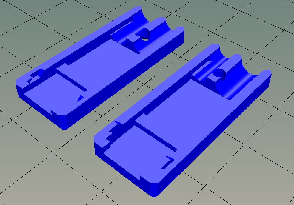
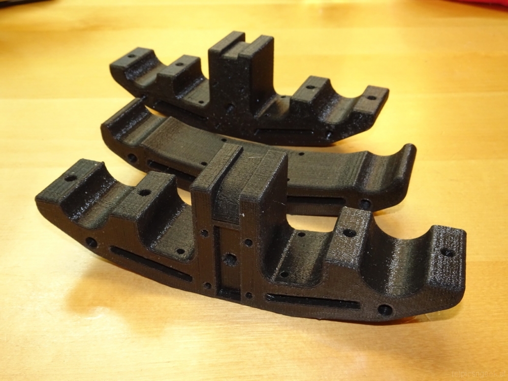
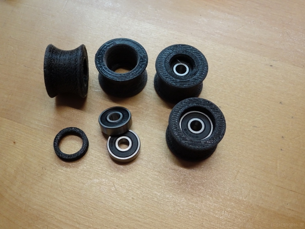
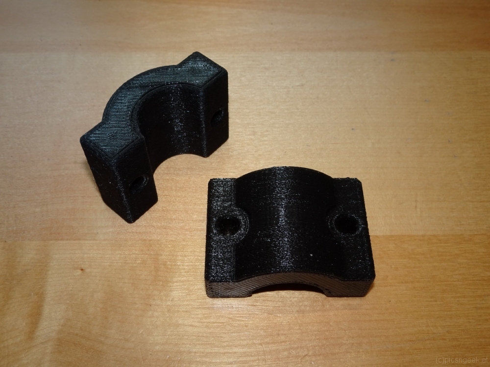
To create a perfect dry-box, a few 3D printed parts as well as a short piece of 40mm water pipe complete the construction. The connection to the printer is established by a PTFE tube, which is fixed in a PC4-6 quick lock.
To ensure a long lasting performance of my filament, I toss in 3-4 bags of silica gel (or silica based cat litter granulate) with 200-300g in total. Now, I may leave my filament installed for weeks without any issues.

3D printer enclosure made of IKEA LACK tables

During refurbishing my office, I ditched the cupboard, where I had my 3D printer set up with some dust protection. The dust protection was a simple transparent table foil. It was sufficient enough to have the printer running. But it was by no means a proper enclosure. Temperature changes as well as air currents could still influence prints.
Now, I wanted to enclose my printer properly. First off, I thought of constructing something entirely from scratch. But upon searching through web pages and blogs, I found several enclosures incorporating IKEA LACK tables. The LACK tables are really cheap and fit almost perfectly the size of my Prusa i3 clone printer.

Upon the next opportunity, I stopped by IKEA and a hardware store to purchase all parts required:
2x IKEA LACK table
3x 50x55cm HDF furniture backing (5mm HDF wood with one side in white foil coating)
1x 45x35cm plywood board, 10-14mm (to mount power supply and Raspberry-Pi)
1x 50x50cm acrylic sheet (4mm strength)
2x hinges
1x door knob
1x magnetic furniture lock

further parts from electronics store or internet order:
2x 50cm LED strips
1x 80mm fan plus cover
2x PC4-6 quicklock tube fixtures
200cm PTFE tube with 2mm inside diameter
1x Mains power connector with switch and fuse
1x RJ45 network connector
1x 12V to USB power adapter with 4A

3D printed parts:
4x IKEA LACK table – leg extender
2x printer mount
1x PC4-6 mounting bracket for print-head
1x case for 12V to USB power adapter
1x mounting brackets for Raspberry-Pi
6x LED strip mounting brackets
1x Web-Cam mount

Construction:

  1. Cut the legs to length
    My enclosure needs to be 50cm in height, inside. The IKEA LACK table legs are 40cm in height. therefore another 10cm legs are required. Use a wood saw to cut 4 legs. As they are hollow, this is done in a moment. The other 4 legs are left as they are.
    Hint: the legs have 2 layers of wood on the pre-drilled end. The other end has no second layer.
  2. Drill holes to the 40cm legs lower end
    Mark the center of the legs and drill a 4mm hole to each of them.
  3. Drill holes to one of the tables top part
    You may drill through the already existing holes, or mark the position on the top side, where the legs will be mounted
  4. Prepare sides
    Use a medium grid sanding paper to chamfer the edges of the HDF sheets, so they fit perfectly.
  5. Prepare connectors and electronics
    The left side is enforced with the plywood board, so that connectors and electronics may be mounted properly. Mark the position of the plywood board, so that it fits between the 2 legs. Screw-mount the board with at least 6 screws.
    Drill (or cut) a hole for the 80mm fan at the rear top position. Don’t forget the 4 mounting holes!
    Then, mark the positions of power and network connectors. Drill and file the holes to size.
    When the holes fit, mount the connectors.
    Next, mount power supply, power adapter and Raspberry. Pay attention to not have your printer collide with one of the parts!
  6. Add PC4-6 connector
    On the left side pane, I have the material feed through on the upper front part. Here, the PTFE tube may flex freely, when the print head moves
  7. Build the LACK tables
  8. Attach LED strips to the upper LACK table
  9. Place 3D printer on lower part
  10. Stack the second LACK table with leg extenders on top of the other
  11. Screw mount the left side
    You may pre-drill 2-3mm holes for the screws, if you like. But the material is soft enough to go without.
  12. Connect all cables to printer, power supply, LED, …
  13. Attach web-cam mount to rear side
    The web cam is best placed approximately 10cm from top
  14. Screw mount rear and right side
  15. Prepare door
    Center the hinges on either left or right front leg. Mark required holes to leg as well as acrylic sheet.
    Mark door knob position on acrylic sheet and opposite leg.
    Drill holes in acrylic sheet with sharp drill bit and low pressure.
  16. Use sink-head screws to mount hinges
  17. Attach door knob and magnetic lock

Tilt Adapter for narrow band solar imaging

Imaging with narrow band H-alpha filters for solar imaging (prominences and chromosphere) requires the light beam to be almost parallel before entering the special interference filter called Etalon filter. This is achieved by i.e. telecentric systems, also extending the focal length by a factor of 2-4x. The sensor protection glass and anti-reflection glass of the camera create reflections with each other and the filter surface. Due to the parallel light beam, these reflections create interference patterns, noticable as so called Newton’s rings in the image. It depends on several different factors like sensor construction (micro lenses, …), exact angle of sensor in optical path, angle between sensor and filter / protection glass, … how strong the Newton’s rings influence the resulting images.

It is possible to reduce or eliminate this in post processing. But any minor shift in the imaging train will make it almost impossible to compensate with flat-field images.
Fortunately, there is one alternative option: tilting the camera by a few degrees (usually up to 5 degrees), to widen the distance of the Newton’s rings, where they are no longer disturbing.

As these tilt adapters have a quite steep price tag, I constructed and printed one myself. I had to create several versions, until I had achieved a proper stability as well as stray light protection. But finally, I have a working tool 🙂
If you are interested in the design, you find the 3D files and description here: https://www.thingiverse.com/thing:4301757

See how much the tilt changes the resulting image!
Hints to the images:
– The blurry look in the image with Newton’s rings results from the alignment algorithm locking on the Newton’s rings instead of surface features
– the adapter attached to the filter is a prototype without stray light protection. Hence a strip of black insulation tape was used for shade

Combined charger and trigger cable for Sony mirrorless cameras like A6400

I often capture time lapse image sequences and do astrophotography. In both applications, a trigger cable and a proper means of powering the camera are essential. Keep in mind, that a fully charged battery usually lasts for no more than 3 hours.
At the moment, the only way to power a Sony mirrorless camera for a whole night or several hours is a dummy battery attached to a power supply (be it a mains power supply or a 7.2V battery driven sollution). With the release of the new models recently, like the A7III or A6400, the camera may also be powered through USB charger during image acquisition. (It may still be possible, that the battery drains, but far far less.)

This is really good news, as a USB power bank will provide the juice to run a whole night or even longer! But there arises one new problem: The external trigger remotes use the same USB port as it is used for charging.
This is possible, as Sony has created the so called Multiport some time back for use with their video cameras. The Multiport is an extended Micro-USB port with a second row of contacts. These contacts provide access to some control as well as audio and video output.

I did some research and came across Multiport connectors with solder pads for all 15 pins. See the pinout in the images at the end of the post.

Sony Multiport Adapter

With such connectors I was able to tailor a dual cable adapter, to charge and trigger the camera at the same time! I took a USB cable with male type A connector and a headphone extender cable with male 3.5mm plug. I chose both cables around 1m in length. This should be long enough in most use cases, but not too long to reduce charging performance.

Combined charger and trigger cable for Sony mirrorless cameras


The 3.5mm plug fits some of my trigger devices. All the others have 2.5mm plugs, for which I have adapter calbes in use. Most computer timer remotes with interchangeable camera plug sold, have a 2.5mm female audio jack. See attached image for the typical pinout.

Soldering the two cables to the tiny solder pads requires a steady hand and experience in soldering. The USB as well as the audio cables have quite thin wires (AWG26 to AWG28, which equals to 0.12 mm² to 0.08 mm²), except the USB power wires (AWG22 or AWG24 in quick charge cables, which equals to 0.32 mm² and 0.20 mm²). The wires are rather stiff. Therefore, aligning the wires to the solder pads may be tricky. It gets especially tricky, if the wires are exposed from the outer isolation for less than a centimeter.
Advice: Always check the finished cable for shorts and proper contact with a multimeter!

Soldered Multiport adapter with USB (bottom) and headphone (top) cables

To reduce wear, which may lead to wires breaking off the solder pads, I designed a connector housing / case. The housing holds the adapter as well as the cables in place. Furthermore, this is the only proper way to handle the connector upon pluggin to / unpluggin from the camera.
The connector case is 3D printed. I share the STL file on Thingiverse here:
https://www.thingiverse.com/thing:4279366

Multiport adapter case – 3D model in 2 parts

Disclaimer:
This is a guide put together as reference for me. If you follow this description, you will do so on your own risk. I may not be held responsible for any damage or injury caused!

Dark Sky Logger – my extended DIY Sky Quality Meter

A few weeks back I had the DIY Sky Quality Meter demo setup working (see here). My primary target in building a Sky Quality Meter was to have a complete all-in-one ambient conditions logging device. So to finalize this project, I added a micro SD-Card reader, real-time clock, barometric pressure sensor and a rechargeable battery. I could manage to squeeze all the code into an Arduino nano :-). With the small footprint of the Arduino nano, I could build a case box (3D-printed) with only 123x68x34mm external dimensions.

One essential part of the case is a chamber for the TAOS TSL237S sensor. The status LEDs of the Arduino did alter darkness readings severely. So any light apart from the night sky has to be shielded from the sensor!
Furthermore, the sensor requires a IR-block and color correction filter, to work comparable to the Unihedron Sky Quality Meter. As described here, Unihedron uses a HOYA CM-500 filter. I could find an almost identical filter, which is now included in the case as front cover of the sensor chamber.

My Arduino code may lack some fine tuning (forgive me, but I will not publish my source code. It would not be fair to Unihedron, who had all the development to build the original SQM device!). But the sensor readings are comparable to the second fraction digit in most cases to the SQM unit I could use for testing. This is sufficiently precise to me. I do refresh all the values (darkness, sensor frequency reading, temperature, humidity, pressure, dew point, calculated altitude, battery voltage, presence of SD card as well as time and date) every 5 seconds. This is someway insane, as a refresh rate of 30 to 60 seconds would still be very high 😉

With a freshly charged 18650 battery, my device may record for more than 50 hours. So even a weekend trip would be no issue.

For all curious folks out there, this is the parts list:
– Arduino nano v3
– DS1307 RTC module
– BME280 – temperature, humidity and pressure module
– Micro-SD Card interface
– 1.3″ OLED Display (128×64 Pixel)
– 18650 Lithium battery carrier with charger and 5V output
– TAOS TSL237S sensor
– 8mm UV-IR Cut filter
– 3D printed case

And this is the device:

Camera slider – build complete :-)

After several hours of designing, 3d printing, drilling, soldering and assembling, my camera slider is ready to use! All components are neatly packed within cases, so that the only wires visible are the power supply from the LiPo battery pack and the shutter release cable to the camera. I have several extensions in mind, like a pan-tilt unit. But for the moment, I will test and use the setup as is. The next improvements will be more on the firmware, for more features: non-linear movement, slow start, slow finish, pre-defined profiles, … for more impressive movies.


Now, concluding the build, I have the following parts in the final setup:

  •  12 U-groove wheels, matching the carbon fiber tubes (3D printed plus ball bearings)
  • 4 wheel carriages, each holding 3 U-groove wheels (3D printed)
  • 1 case for the microcontroller and motor driver (3D printed)
  • 1 case for shutter release, power supply and connectors (3D printed)
  • 1 hand-controller case (3D printed)
  • 1 battery bracket (3D printed)
  • 2 end-assemblies (5 parts each, 3D printed)
  • 2 supports (3 parts each, 3D printed)
  • 1 NEMA17 stepper motor
  • 1 A4988 stepper motor driver
  • 1 Arduino Nano (Atmel 328 microcontroller)
  • 1 4×20 LCD
  • 1 Joystick module
  • 1 DC-DC converter
  • 2 micro switches with long lever as end switches
  • GT2 10mm timing belt with wire reinforcement
  • 1 GT2 10mm 20 teeth pulley wheel
  • 4 GT2 10mm idler wheels
  • A whole bunch of M3 to M6 screws and nuts
  • 40x3mm flat aluminium
  • 30x50x3mm L-shaped aluminium
  • carbon fiber tubes

The project was really a fun to make. Even more, the resulting slider provides flexibility and transportability! I may configure the slider in any length, depending on the available tubes. The tubes I use, are 37cm in length and have aluminium screw-in adapters to fit one to the other. I have a bag, which I used as personal item in air travel. The bag holds the complete setup for up to 5 meters (exkluding tripods). The bag weighs in at approximately 5kg – so it is a light weight setup for the length possible.

Damascus knife – building the handle

A few weeks ago, I built a damaskus knife blade (see Damascus knive workshop). Now I finally had time to build the handle. Part of the delay accounted for the decision in material and design of the handle. After some serious research and window shopping, I found the perfect combination I would love to have: desert iron wood and silver.
Desert iron wood is a very dense and hard wood. The core parts have a deep red color with wonderful dark texture. But it is not at all easy to find a piece at reasonable prices. Luckily I found an online store, offering a block of desert iron wood with matching size and texture to my likings.
The bolster shall be like a cap, continuing the shape of the handle. As a material I use sterling silver.

The shape of the handle should become rather minimalistic. Further more, I wanted to have some resemblance to traditional Japanese handles. Therefore I chose a prolongued octagonal shape, which gradually gains a bit in height from the bolster to the end.

To build the handle, I started with the wood. I drilled a hole at the exact position to center the blade. Then I used small files to match the hole with the tang, which has a rectangular shape and is a bit off-centered to the rest of the blade. This was really time consuming, as the desert iron wood clogged the files within a few strokes. But finally, after a few hours of work, I had a perfect fit for the tang. I let approximately 5mm of the tang still protruding the handle, to have more strength in the final assembly by hammering the handle on to the blade.
The next step was to make the recessed front, where the bolster will fit in. I cut a line at exactly 10mm from the front edge. Then I filed away 1mm of wood, as I will use 1mm sheet sterling silver. From a strip of 11mm width I formed a ring with an octagonal shape matching the handle, using parallel pliers. The ring is soldered with hard sterling silver solder. After filing and sanding the edges to have perfectly flat sides, I cut a sheet of silver with a bit of excess border. The ring is soldered to the sheet, again using hard solder. After cleaning and filing away the excess material, I could drill and file the hole for the tang. This again was a bit time consuming, to create a perfect fit…

Finally, I sanded and polished the silver bolster, gave the desert iron wood a last fine sanding. Then I mixed a bit of epoxy with desert iron wood file dust. I added glue to the bolster and into the hole for the tang. So I would have a really strong bonding betreen all the parts. I hammered the bolster to the handle (which was only necessary for the final 2mm). Following immediately I inserted the knifes tang to the handle. Using a rubber hammer, I pushed the tang into the final position within the handle.
Meanwhile I set an oven to approximately 70° Celsius for increased strentgh and faster hardening of the epoxy. After cleaning away any excess epoxy with acetone, I set the whole knife in the oven for curing.

Hint: If there is any epoxy pushed out of the joints during curing, you may use a small soldering iron to work the exopy off the surface. The remaining thin film of epoxy may be removed with acetone. If you are careful, you will most likely have a scratch free surface afterwards!

The last thing to do is a thin coating of hard oil.
After more than 20 hours of work (including forging the blade), the knife is ready 🙂 The final result is a perfectly balanced knife due to the heavy wood handle. The center of balance lies exatly in front of the bolster. The blade will hopefully last for a very long time and provide perfect cuts due to approximately 56-58 HRC.

Motorized camera slider

For quite some time I would like to create night time movies in hyperlapses. For me, the most stunning results may be created by moving the camera along a linear path by the use of motorized sliders. Motorized sliders, which are more than 2 meters long, have an impressive price tag. Further more, these tools are bulky and heavy, especially when the setup attached to weighs in a few kilos.
Therefore I decided to build my own with a few goals in mind:

  • light weight
  • portable
  • variable length
  • suitable for a load of a few kilos
  • wider range of speeds
  • extendable for rotation axis
  • direct control for camera(s)

To achieve all or most of these goals, I came up with a design built around carbon fiber tubes with aluminum screw-in fixtures. Appropriate tubes may be built from scratch or are readily available for camera gimbals. I chose the camera gimbal extensions, as there is no big price difference to buying stock material. Further more, they come in a handy size of +/- 40cm in length.
The end supports will have to hold the tubes as well as a gear belt, along which the slider cart will be driven. For long setups, I created supports, to prevent bending and excessive stress to the tubes. Both types of support will have legs as well as tripod mount screw holes (3/8 UNC thread)
The slider cart consists of 4 blocks holding 3 pulley wheels each. The blocks are attached to a base plate (in test setup a plywood sheet). In the middle of the base plate lies the motor unit consisting of a steper motor and 4 guiding wheels to create enough tension for the gear belt to be driven by the motor.

All in all, the shopping list is really limited, as most parts were 3D-printed. What I had to purchase or use (most parts were already to be found in the workshop) was:

  • carbon fiber rods (at least 8)
  • 24 ball bearings type 626 2RS (6x19x6 mm)
  • GT2x10mm belt matching the desired length
  • GT2 20 tooth drive gear
  • 4 guide wheels without teeth for 10mm belt
  • 1 NEMA 14 stepper motor, <3V nominal voltage
  • several M5 and M6 screws, washers and nuts
  • 3/8 UNC thread taper
  • approximately 0.5m of 40x3mm Aluminum sheet
  • 25cm of 30x50x3mm Aluminum L shaped profile
  • Arduino, Stepper motor controller like A4988, 12-18V (lithium) battery
  • 1 can of rubber spray like Plasti-Dip (c)

Most of the time I spent was in CAD constructing the parts. Printing took about 3 days. The pulley wheels have to be sanded for a smooth surface before coating with rubber. The remaining time was spent in cutting, drilling and tapering the aluminum parts, before all parts could be attached together.

The first test run was more than pleasing. See for yourself:

The next thing to do is to create a control box with all the features implemented for every day use 🙂

This site uses cookies. By continuing to use the site (including navigation and scrolling), you agree to the use of cookies. more information

The cookie settings on this website are set to "allow cookies" to give you the best browsing experience possible. If you continue to use this website without changing your cookie settings or you click "Accept" below then you are consenting to this.

Close