Skywatcher AZ-EQ6 stalls during Go-To – Power supply issues

Earlier this year I got a lucky owner of a 10 inch carbon fiber newtonian telescope. The scope weighs in around 13kg. So I thought, this would fit perfectly within the capabilities of my AZ-EQ6 mount. Well, yes, by numbers (the AZ-EQ6 payload is 20kg), but not in my setup.
First of all, I had to add a third counter weight on the extension bar. So an overall counter weight of 15kg has to be added for these big scopes. Second, the mount became unreliable, as in Go-To movements, the mount stalled at some instances with a squeaking noise.
The noise is easily identified as the stepper motors skipping steps and not being able to drive the mount to the desired position. The mount won’t be harmed in any way. But the alignment will be gone for good. So you have to reset the mount and align with the sky again. Or, if this happens during alignment, you won’t be able to tell or teach the mount the actual sky model.

Additional information: Why do stepper motors skip steps?
A stepper motor, as built into the AZ-EQ6, consists of 2 static coils and a geared permanent magnet on the rotor. When the coils are powered in the right pattern, the generated magnetic field causes the rotor to move (in most cases 1.8° per full step). These coils are loaded in forward and reverse alternately. During the loading phase of a coil, the coil poses a resistance. This resistance limits the current. The possible current combined with a given voltage (supply voltage) defines the available power to load the coil and generate the magnetic field to move the rotor. How strong the magnetic field has to be is set by the inertia of the motor itself, the desired speed and the attached load. Loading the coil takes a bit of time (in the range of 100 microseconds to a few milliseconds). To achieve the desired movement (mechanical work in given time), a certain minimum of voltage, current and load time has to be provided.
If at least one of the parameters does not meet the requirements, the motor will not be able to fulfill the movement. So the stepper motor will not fully move to the next step “position”. When the motor controller begins to change the supply pattern of the coils before the rotor reaches a sufficient angle towards the next step position, the rotor might be pulled back towards the previous matching position. So the rotor will be trapped in a narrow range of steps, jumping back and forth.

I was driving the mount with a 12V 20A power supply at home. When on the mountain top, I used a 12V sealed lead acid gel battery. All was fine, using scopes with less than 10kg (and only 2 counter weigth discs). But with the 13kg scope and extra 5kg counter weight, I added too much inertia to the drive system. So, as I want to use the 10 inch scope with the AZ-EQ6, and the AZ-EQ6 has no option to reduce Go-To speed, there is only one option to improve the setup: increase the voltage!
The manual says, Input Voltage: 11-16V DC, 4A. I tested the mount with a lab power supply at 15V. The mount was happy with the provided power. Further more, all Go-To movements completed without and problem! Sollution found!
For home use, I could find a quite cheap 15V 4A supply (15V supplies are easier to find than 16V supplies). For mobile use, there is no reasonable power pack, providing 15V. So I purchased a powerful 120W DC-DC boost converter from 12V up to 15V, which will run from car- or other 12V battery. (This is a temporary setup, until my mobile lithium battery based astro power supply is ready to use)
Both supplies got their GX12-2 connector to be plugged in to the AZ-EQ6 supply terminal…


Combined charger and trigger cable for Sony mirrorless cameras like A6400

I often capture time lapse image sequences and do astrophotography. In both applications, a trigger cable and a proper means of powering the camera are essential. Keep in mind, that a fully charged battery usually lasts for no more than 3 hours.
At the moment, the only way to power a Sony mirrorless camera for a whole night or several hours is a dummy battery attached to a power supply (be it a mains power supply or a 7.2V battery driven sollution). With the release of the new models recently, like the A7III or A6400, the camera may also be powered through USB charger during image acquisition. (It may still be possible, that the battery drains, but far far less.)

This is really good news, as a USB power bank will provide the juice to run a whole night or even longer! But there arises one new problem: The external trigger remotes use the same USB port as it is used for charging.
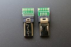
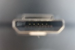
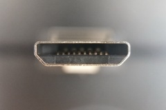
This is possible, as Sony has created the so called Multiport some time back for use with their video cameras. The Multiport is an extended Micro-USB port with a second row of contacts. These contacts provide access to some control as well as audio and video output.

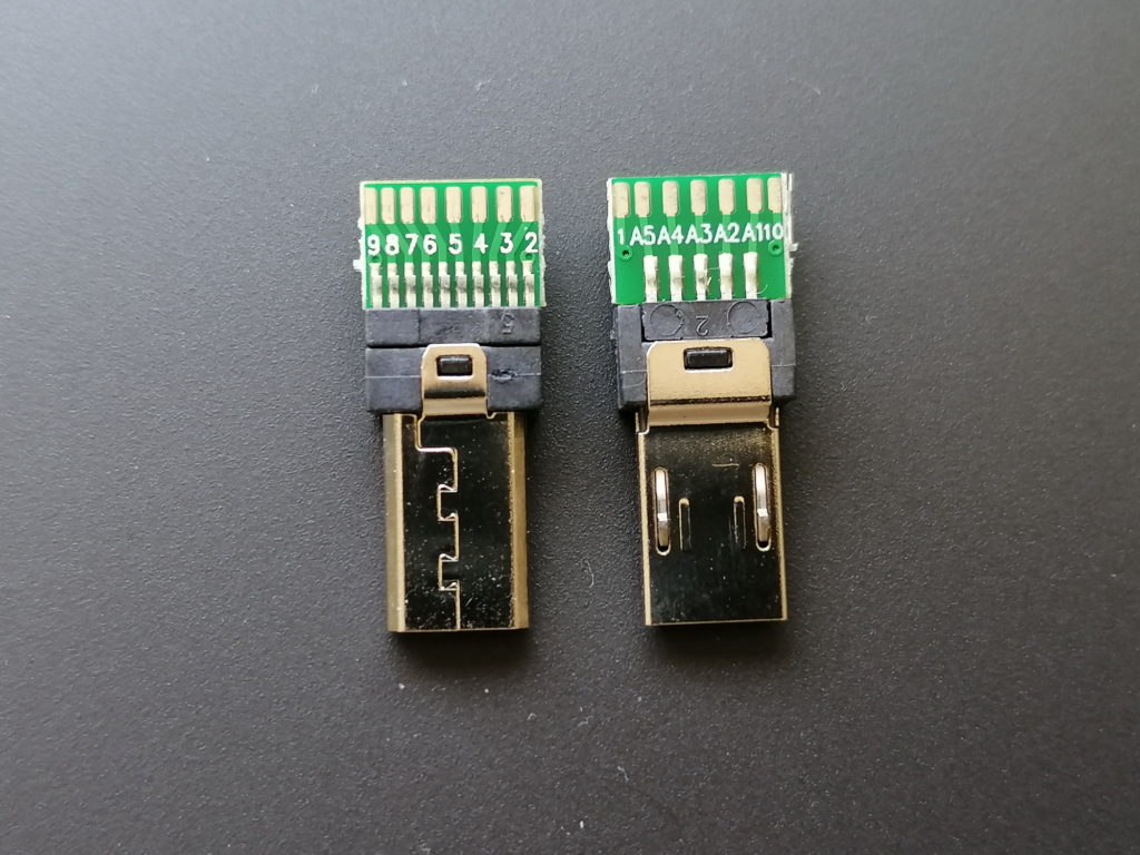
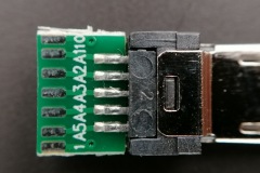
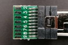
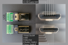
I did some research and came across Multiport connectors with solder pads for all 15 pins. See the pinout in the images at the end of the post.

Sony Multiport Adapter

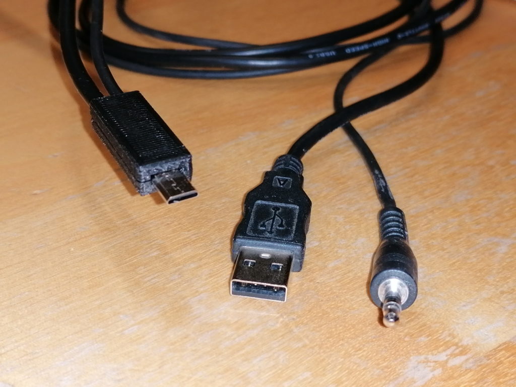
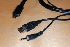
With such connectors I was able to tailor a dual cable adapter, to charge and trigger the camera at the same time! I took a USB cable with male type A connector and a headphone extender cable with male 3.5mm plug. I chose both cables around 1m in length. This should be long enough in most use cases, but not too long to reduce charging performance.

Combined charger and trigger cable for Sony mirrorless cameras


The 3.5mm plug fits some of my trigger devices. All the others have 2.5mm plugs, for which I have adapter calbes in use. Most computer timer remotes with interchangeable camera plug sold, have a 2.5mm female audio jack. See attached image for the typical pinout.

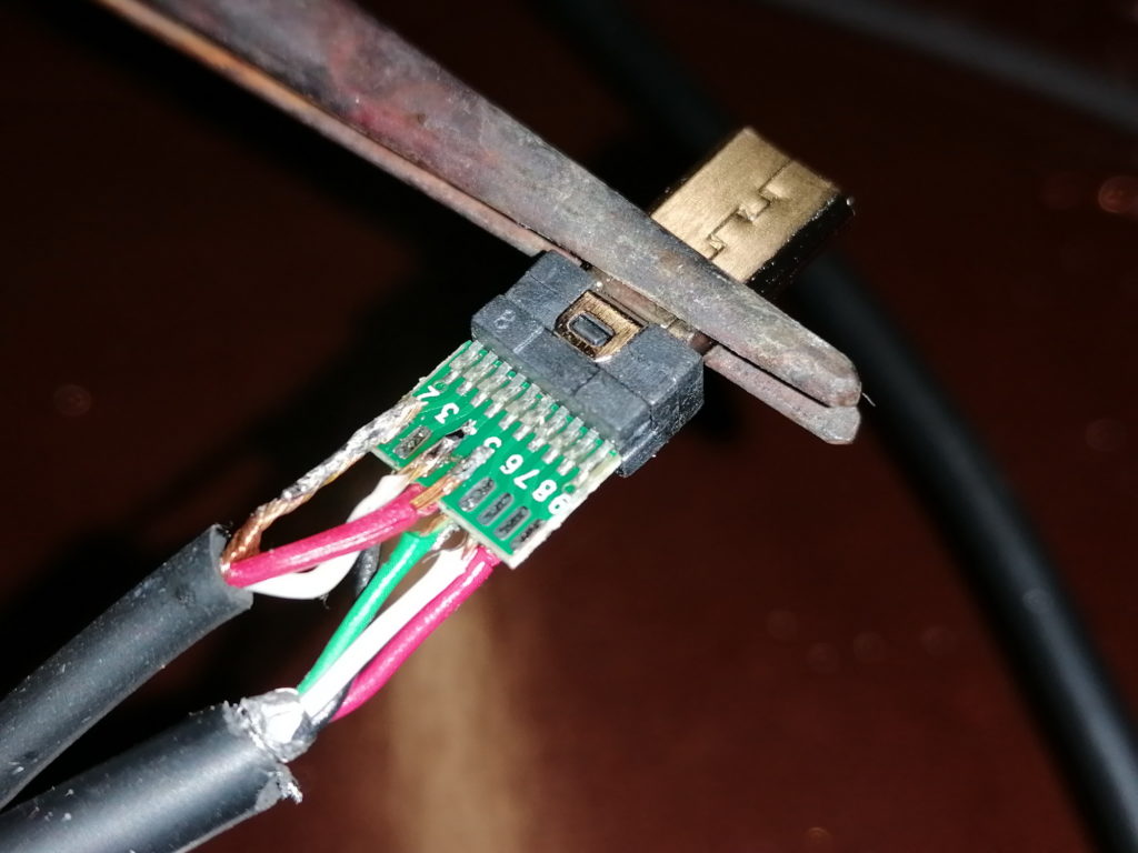
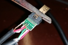
Soldering the two cables to the tiny solder pads requires a steady hand and experience in soldering. The USB as well as the audio cables have quite thin wires (AWG26 to AWG28, which equals to 0.12 mm² to 0.08 mm²), except the USB power wires (AWG22 or AWG24 in quick charge cables, which equals to 0.32 mm² and 0.20 mm²). The wires are rather stiff. Therefore, aligning the wires to the solder pads may be tricky. It gets especially tricky, if the wires are exposed from the outer isolation for less than a centimeter.
Advice: Always check the finished cable for shorts and proper contact with a multimeter!

Soldered Multiport adapter with USB (bottom) and headphone (top) cables

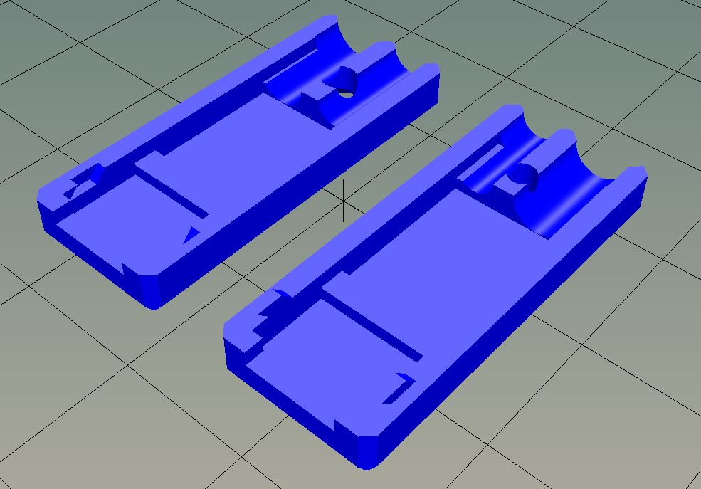
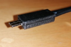
To reduce wear, which may lead to wires breaking off the solder pads, I designed a connector housing / case. The housing holds the adapter as well as the cables in place. Furthermore, this is the only proper way to handle the connector upon pluggin to / unpluggin from the camera.
The connector case is 3D printed. I share the STL file on Thingiverse here:
https://www.thingiverse.com/thing:4279366

Multiport adapter case – 3D model in 2 parts

Disclaimer:
This is a guide put together as reference for me. If you follow this description, you will do so on your own risk. I may not be held responsible for any damage or injury caused!

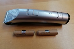
Battery replacement of Panasonic hair trimmer, Models ER1410 and similar with standard AA NiMH batteries

I own a Panasonic ER1410 hair trimmer. Unfortunately, after a few years of service, the batteries did no longer charge. I continued to use it in wired mode. But it is by far no comfort to have the cable dangling around. So after some time I decided to check for a battery replacement.
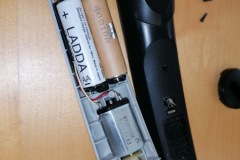
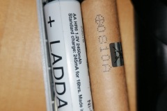
There are several offers for a set of replacement batteries available online. But these are quite expensive. Luckily the batteries are NiMH rechargable ones in AA / Mignon size. The only difference from the standard AA batteries is a pin like connector on both poles, which slide in a metal groove for contact. The design is replacement-friendly, as the batteries are not soldered to the PCB. Instead, there is a 2 slot battery carrier, designed for the pin like connectors.
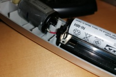
When a standard AA rechargable battery is inserted to the battery carrier, the battery has not quite good contact. To fix this, use a set of pliers to bend the metal contacts a bit. The batteries will have sufficient contact and the hair trimmer will work well!

Here are the steps I had to follow:
1. remove trimmer cartrige
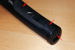
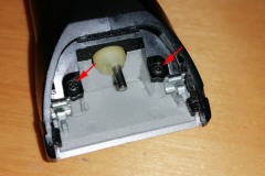
2. unscrew all 5 screws (see photo for positions)
3. remove black round part at charger connector
4. lift black bottom part
5. remove batteries and remember polarities!
6. bend metal contacts inwards with pliers until new batteries have firm contact
7. insert new 1.2V NiMH AA batteries (check polarity!)
8. close trimmer and fasten all 5 screws
9. test operation and charging

Disclaimer:
This is a guide put together as reference for me. If you follow this description, you will do so on your own risk. I will not be held responsible for any damage or injury caused by a DIY repair. Be aware, that using wrong batteries (i.e. non-rechargable, wrong type / Voltage, …) or batteries installed wrong may cause serious injuries and carry a high risk of fire!

Dark Sky Logger – my extended DIY Sky Quality Meter

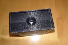
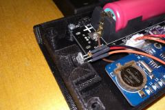
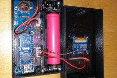
A few weeks back I had the DIY Sky Quality Meter demo setup working (see here). My primary target in building a Sky Quality Meter was to have a complete all-in-one ambient conditions logging device. So to finalize this project, I added a micro SD-Card reader, real-time clock, barometric pressure sensor and a rechargeable battery. I could manage to squeeze all the code into an Arduino nano :-). With the small footprint of the Arduino nano, I could build a case box (3D-printed) with only 123x68x34mm external dimensions.

One essential part of the case is a chamber for the TAOS TSL237S sensor. The status LEDs of the Arduino did alter darkness readings severely. So any light apart from the night sky has to be shielded from the sensor!
Furthermore, the sensor requires a IR-block and color correction filter, to work comparable to the Unihedron Sky Quality Meter. As described here, Unihedron uses a HOYA CM-500 filter. I could find an almost identical filter, which is now included in the case as front cover of the sensor chamber.

My Arduino code may lack some fine tuning (forgive me, but I will not publish my source code. It would not be fair to Unihedron, who had all the development to build the original SQM device!). But the sensor readings are comparable to the second fraction digit in most cases to the SQM unit I could use for testing. This is sufficiently precise to me. I do refresh all the values (darkness, sensor frequency reading, temperature, humidity, pressure, dew point, calculated altitude, battery voltage, presence of SD card as well as time and date) every 5 seconds. This is someway insane, as a refresh rate of 30 to 60 seconds would still be very high 😉

With a freshly charged 18650 battery, my device may record for more than 50 hours. So even a weekend trip would be no issue.

For all curious folks out there, this is the parts list:
– Arduino nano v3
– DS1307 RTC module
– BME280 – temperature, humidity and pressure module
– Micro-SD Card interface
– 1.3″ OLED Display (128×64 Pixel)
– 18650 Lithium battery carrier with charger and 5V output
– TAOS TSL237S sensor
– 8mm UV-IR Cut filter
– 3D printed case

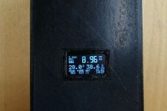
And this is the device:

My DIY Sky Quality Meter – first test

A few times in the past I have seen charts of the dark sky quality for astronomical use. Especially during a visit of the University astronomy department I had the chance to talk with one of the facilities operators. This made me curious about how they quantify the night sky quality.

Upon further research I found the widely used Sky Quality Meter by Unihedron. It is a small box measuring the sky brightness by means of a light sensor with corresponding frequency output. When I could find a distributor selling these sensors for a good price, I was up to building my own one.
My concept was to use a arduino style micro controller and build a sky quality meter together with weather data (temperature, pressure, humidity) recording device. The device should save every 10-30 seconds the data collected. And it should last for at least one whole night running on a small(er) battery like AA or 18650 lithium type.

The hardware part was quite easy to accomplish. I simply had to connect a couple of wires from the micro controller to the sensors and other components. The harder part was to create a proper software, fulfilling all my needs. I had to find a way to
1) cope with the frequency range of 0.01Hz to 1MHz
2) fit all the code within the small memory
3) calculate sky quality and calibrate device to a reference device

Luckily, apart from a reasonably well described device on the Unihedron web-site, I could borrow one Sky Quality Meter from a fellow astronomy club member. So I had a reference device to compare and calibrate my device.

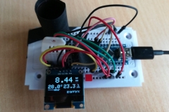
Here is the test setup. The readings are already very close to the original device!

This site uses cookies. By continuing to use the site (including navigation and scrolling), you agree to the use of cookies. more information

The cookie settings on this website are set to "allow cookies" to give you the best browsing experience possible. If you continue to use this website without changing your cookie settings or you click "Accept" below then you are consenting to this.

Close