
I often capture time lapse image sequences and do astrophotography. In both applications, a trigger cable and a proper means of powering the camera are essential. Keep in mind, that a fully charged battery usually lasts for no more than 3 hours.
At the moment, the only way to power a Sony mirrorless camera for a whole night or several hours is a dummy battery attached to a power supply (be it a mains power supply or a 7.2V battery driven sollution). With the release of the new models recently, like the A7III or A6400, the camera may also be powered through USB charger during image acquisition. (It may still be possible, that the battery drains, but far far less.)
This is really good news, as a USB power bank will provide the juice to run a whole night or even longer! But there arises one new problem: The external trigger remotes use the same USB port as it is used for charging.
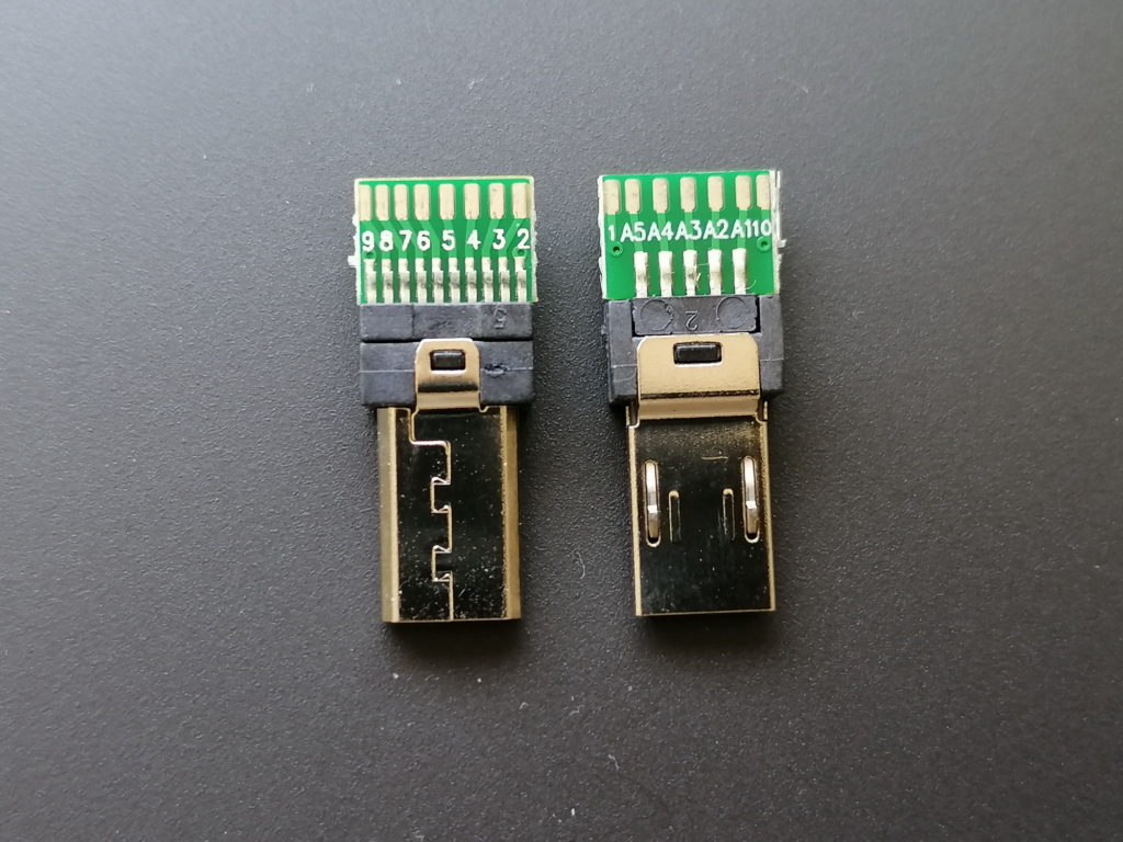
This is possible, as Sony has created the so called Multiport some time back for use with their video cameras. The Multiport is an extended Micro-USB port with a second row of contacts. These contacts provide access to some control as well as audio and video output.
I did some research and came across Multiport connectors with solder pads for all 15 pins. See the pinout in the images at the end of the post.
With such connectors I was able to tailor a dual cable adapter, to charge and trigger the camera at the same time! I took a USB cable with male type A connector and a headphone extender cable with male 3.5mm plug. I chose both cables around 1m in length. This should be long enough in most use cases, but not too long to reduce charging performance.
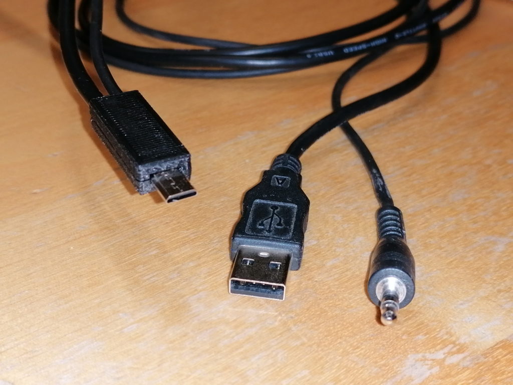
The 3.5mm plug fits some of my trigger devices. All the others have 2.5mm plugs, for which I have adapter calbes in use. Most computer timer remotes with interchangeable camera plug sold, have a 2.5mm female audio jack. See attached image for the typical pinout.
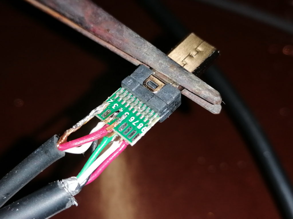
Soldering the two cables to the tiny solder pads requires a steady hand and experience in soldering. The USB as well as the audio cables have quite thin wires (AWG26 to AWG28, which equals to 0.12 mm² to 0.08 mm²), except the USB power wires (AWG22 or AWG24 in quick charge cables, which equals to 0.32 mm² and 0.20 mm²). The wires are rather stiff. Therefore, aligning the wires to the solder pads may be tricky. It gets especially tricky, if the wires are exposed from the outer isolation for less than a centimeter.
Advice: Always check the finished cable for shorts and proper contact with a multimeter!
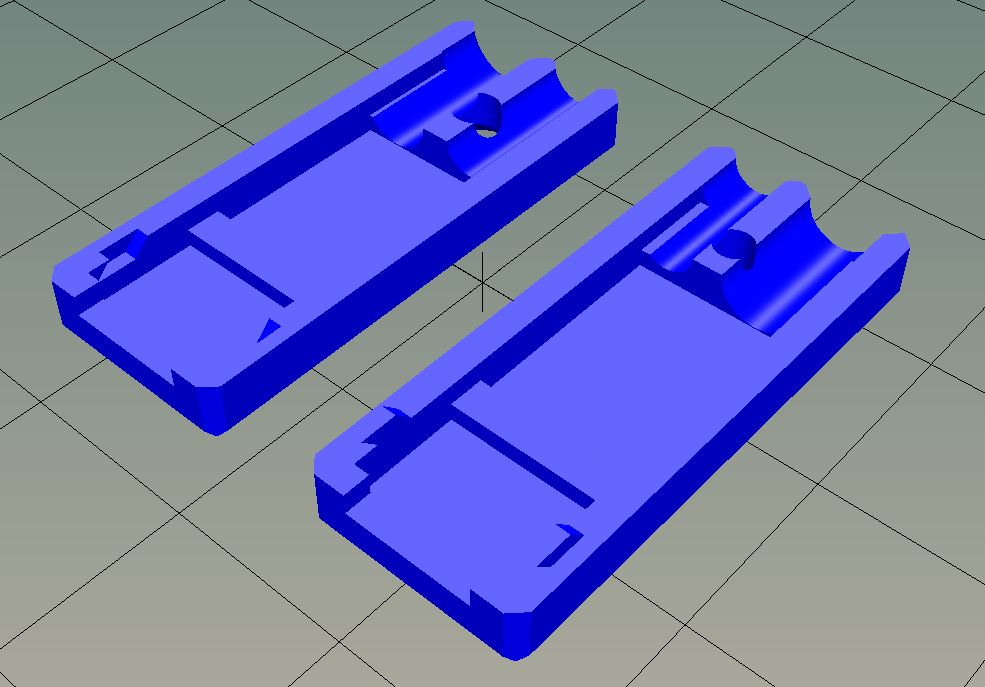
To reduce wear, which may lead to wires breaking off the solder pads, I designed a connector housing / case. The housing holds the adapter as well as the cables in place. Furthermore, this is the only proper way to handle the connector upon pluggin to / unpluggin from the camera.
The connector case is 3D printed. I share the STL file on Thingiverse here:
https://www.thingiverse.com/thing:4279366


Disclaimer:
This is a guide put together as reference for me. If you follow this description, you will do so on your own risk. I may not be held responsible for any damage or injury caused!