Dry-Box for 3D printer filament

When 3D printer filament is exposed to normal ambient humidity, the material gets brittle and hard – if not impossible – to print. Depending on the filament and ambient humidity, it may take several hours to days, until an effect may be noticed. To avoid – or at least extend the time – until printing get’s affected, filament should be stored in dry conditions.

One proposed way is, to re-pack the filament as soon as printing has finished. This method may be adequate for occasional printer habits. But still, after several uses, the filament shows negative influence caused by humidity.

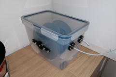
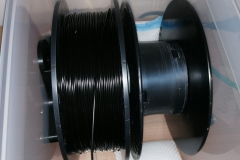
A far more practical way (in my opinion) is, to install the filament in a dry-box, from which the printer is fed the material without unpacking. Therefore, an air-tight container, sufficiently large enough, is required.
There are some types of dry-boxes commercially available. Some have included heating, to even better keep the filament in optimum conditions. But most of them bare a rather steep price tag (70-100 EUR).

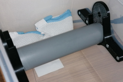
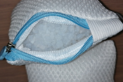
So, why not build one yourself? Even better, if it costs less than 20 EUR? Thanks to IKEA, one of the recent additions to their kitchen supplies is the 10.6L 365+ food container. The container is air-tight, which is perfect for a dry-box. This container is large enough to fit 2x 1kg spools of filament. And the best part is, it costs 8 EUR at the time of writing.

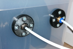
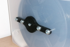
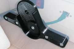
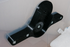
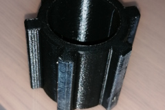
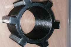
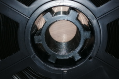
To create a perfect dry-box, a few 3D printed parts as well as a short piece of 40mm water pipe complete the construction. The connection to the printer is established by a PTFE tube, which is fixed in a PC4-6 quick lock.
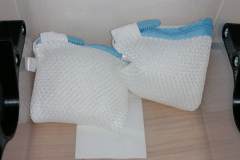
To ensure a long lasting performance of my filament, I toss in 3-4 bags of silica gel (or silica based cat litter granulate) with 200-300g in total. Now, I may leave my filament installed for weeks without any issues.


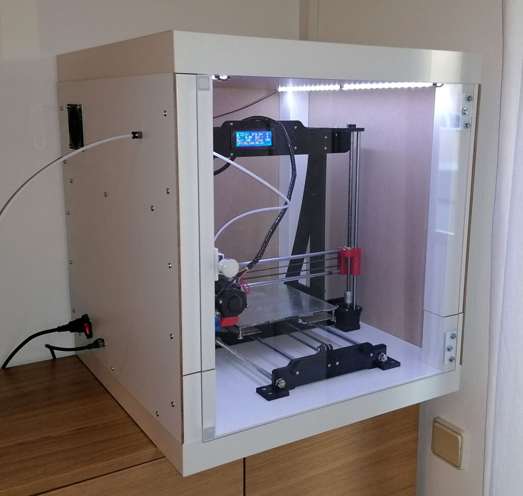
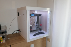
3D printer enclosure made of IKEA LACK tables

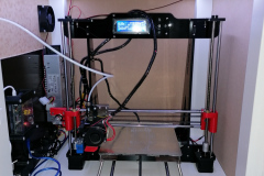
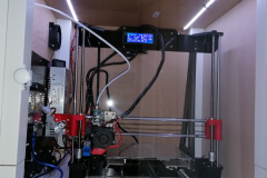
During refurbishing my office, I ditched the cupboard, where I had my 3D printer set up with some dust protection. The dust protection was a simple transparent table foil. It was sufficient enough to have the printer running. But it was by no means a proper enclosure. Temperature changes as well as air currents could still influence prints.
Now, I wanted to enclose my printer properly. First off, I thought of constructing something entirely from scratch. But upon searching through web pages and blogs, I found several enclosures incorporating IKEA LACK tables. The LACK tables are really cheap and fit almost perfectly the size of my Prusa i3 clone printer.
Upon the next opportunity, I stopped by IKEA and a hardware store to purchase all parts required:
2x IKEA LACK table
3x 50x55cm HDF furniture backing (5mm HDF wood with one side in white foil coating)
1x 45x35cm plywood board, 10-14mm (to mount power supply and Raspberry-Pi)
1x 50x50cm acrylic sheet (4mm strength)
2x hinges
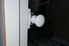
1x door knob
1x magnetic furniture lock

further parts from electronics store or internet order:
2x 50cm LED strips
1x 80mm fan plus cover
2x PC4-6 quicklock tube fixtures
200cm PTFE tube with 2mm inside diameter
1x Mains power connector with switch and fuse
1x RJ45 network connector
1x 12V to USB power adapter with 4A

3D printed parts:
4x IKEA LACK table – leg extender
2x printer mount
1x PC4-6 mounting bracket for print-head
1x case for 12V to USB power adapter
1x mounting brackets for Raspberry-Pi
6x LED strip mounting brackets
1x Web-Cam mount

Construction:

  1. Cut the legs to length
    My enclosure needs to be 50cm in height, inside. The IKEA LACK table legs are 40cm in height. therefore another 10cm legs are required. Use a wood saw to cut 4 legs. As they are hollow, this is done in a moment. The other 4 legs are left as they are.
    Hint: the legs have 2 layers of wood on the pre-drilled end. The other end has no second layer.
  2. Drill holes to the 40cm legs lower end
    Mark the center of the legs and drill a 4mm hole to each of them.
  3. Drill holes to one of the tables top part
    You may drill through the already existing holes, or mark the position on the top side, where the legs will be mounted
  4. Prepare sides
    Use a medium grid sanding paper to chamfer the edges of the HDF sheets, so they fit perfectly.
  5. Prepare connectors and electronics
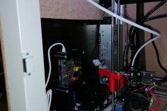
    The left side is enforced with the plywood board, so that connectors and electronics may be mounted properly. Mark the position of the plywood board, so that it fits between the 2 legs. Screw-mount the board with at least 6 screws.
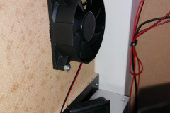
    Drill (or cut) a hole for the 80mm fan at the rear top position. Don’t forget the 4 mounting holes!
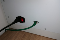
    Then, mark the positions of power and network connectors. Drill and file the holes to size.
    When the holes fit, mount the connectors.
    Next, mount power supply, power adapter and Raspberry. Pay attention to not have your printer collide with one of the parts!
  6. Add PC4-6 connector
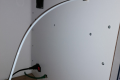
    On the left side pane, I have the material feed through on the upper front part. Here, the PTFE tube may flex freely, when the print head moves
  7. Build the LACK tables
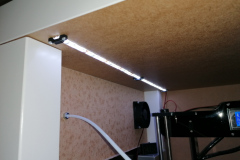
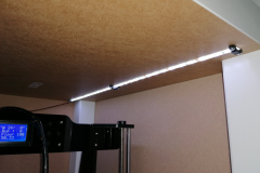
  8. Attach LED strips to the upper LACK table
  9. Place 3D printer on lower part
  10. Stack the second LACK table with leg extenders on top of the other
  11. Screw mount the left side
    You may pre-drill 2-3mm holes for the screws, if you like. But the material is soft enough to go without.
  12. Connect all cables to printer, power supply, LED, …
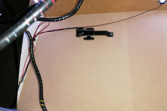
  13. Attach web-cam mount to rear side
    The web cam is best placed approximately 10cm from top
  14. Screw mount rear and right side
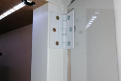
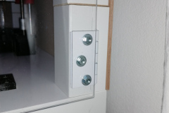
  15. Prepare door
    Center the hinges on either left or right front leg. Mark required holes to leg as well as acrylic sheet.
    Mark door knob position on acrylic sheet and opposite leg.
    Drill holes in acrylic sheet with sharp drill bit and low pressure.
  16. Use sink-head screws to mount hinges
  17. Attach door knob and magnetic lock

Skywatcher AZ-EQ6 stalls during Go-To – Power supply issues

Earlier this year I got a lucky owner of a 10 inch carbon fiber newtonian telescope. The scope weighs in around 13kg. So I thought, this would fit perfectly within the capabilities of my AZ-EQ6 mount. Well, yes, by numbers (the AZ-EQ6 payload is 20kg), but not in my setup.
First of all, I had to add a third counter weight on the extension bar. So an overall counter weight of 15kg has to be added for these big scopes. Second, the mount became unreliable, as in Go-To movements, the mount stalled at some instances with a squeaking noise.
The noise is easily identified as the stepper motors skipping steps and not being able to drive the mount to the desired position. The mount won’t be harmed in any way. But the alignment will be gone for good. So you have to reset the mount and align with the sky again. Or, if this happens during alignment, you won’t be able to tell or teach the mount the actual sky model.

Additional information: Why do stepper motors skip steps?
A stepper motor, as built into the AZ-EQ6, consists of 2 static coils and a geared permanent magnet on the rotor. When the coils are powered in the right pattern, the generated magnetic field causes the rotor to move (in most cases 1.8° per full step). These coils are loaded in forward and reverse alternately. During the loading phase of a coil, the coil poses a resistance. This resistance limits the current. The possible current combined with a given voltage (supply voltage) defines the available power to load the coil and generate the magnetic field to move the rotor. How strong the magnetic field has to be is set by the inertia of the motor itself, the desired speed and the attached load. Loading the coil takes a bit of time (in the range of 100 microseconds to a few milliseconds). To achieve the desired movement (mechanical work in given time), a certain minimum of voltage, current and load time has to be provided.
If at least one of the parameters does not meet the requirements, the motor will not be able to fulfill the movement. So the stepper motor will not fully move to the next step “position”. When the motor controller begins to change the supply pattern of the coils before the rotor reaches a sufficient angle towards the next step position, the rotor might be pulled back towards the previous matching position. So the rotor will be trapped in a narrow range of steps, jumping back and forth.

I was driving the mount with a 12V 20A power supply at home. When on the mountain top, I used a 12V sealed lead acid gel battery. All was fine, using scopes with less than 10kg (and only 2 counter weigth discs). But with the 13kg scope and extra 5kg counter weight, I added too much inertia to the drive system. So, as I want to use the 10 inch scope with the AZ-EQ6, and the AZ-EQ6 has no option to reduce Go-To speed, there is only one option to improve the setup: increase the voltage!
The manual says, Input Voltage: 11-16V DC, 4A. I tested the mount with a lab power supply at 15V. The mount was happy with the provided power. Further more, all Go-To movements completed without and problem! Sollution found!
For home use, I could find a quite cheap 15V 4A supply (15V supplies are easier to find than 16V supplies). For mobile use, there is no reasonable power pack, providing 15V. So I purchased a powerful 120W DC-DC boost converter from 12V up to 15V, which will run from car- or other 12V battery. (This is a temporary setup, until my mobile lithium battery based astro power supply is ready to use)
Both supplies got their GX12-2 connector to be plugged in to the AZ-EQ6 supply terminal…

Combined charger and trigger cable for Sony mirrorless cameras like A6400

I often capture time lapse image sequences and do astrophotography. In both applications, a trigger cable and a proper means of powering the camera are essential. Keep in mind, that a fully charged battery usually lasts for no more than 3 hours.
At the moment, the only way to power a Sony mirrorless camera for a whole night or several hours is a dummy battery attached to a power supply (be it a mains power supply or a 7.2V battery driven sollution). With the release of the new models recently, like the A7III or A6400, the camera may also be powered through USB charger during image acquisition. (It may still be possible, that the battery drains, but far far less.)

This is really good news, as a USB power bank will provide the juice to run a whole night or even longer! But there arises one new problem: The external trigger remotes use the same USB port as it is used for charging.
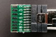
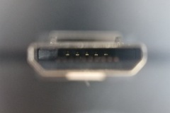
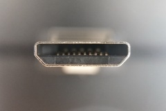
This is possible, as Sony has created the so called Multiport some time back for use with their video cameras. The Multiport is an extended Micro-USB port with a second row of contacts. These contacts provide access to some control as well as audio and video output.

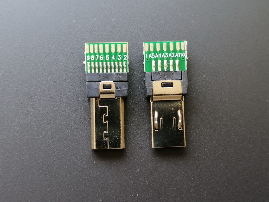
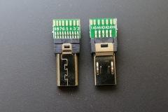
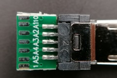
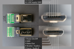
I did some research and came across Multiport connectors with solder pads for all 15 pins. See the pinout in the images at the end of the post.

Sony Multiport Adapter

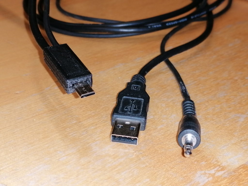
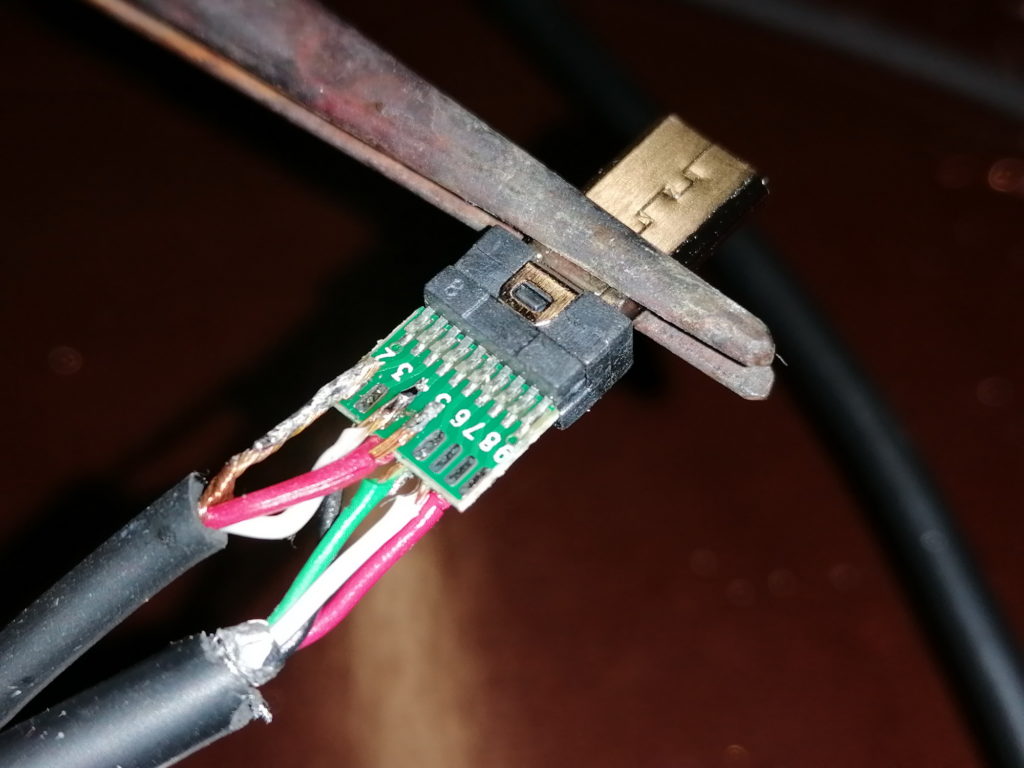
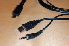
With such connectors I was able to tailor a dual cable adapter, to charge and trigger the camera at the same time! I took a USB cable with male type A connector and a headphone extender cable with male 3.5mm plug. I chose both cables around 1m in length. This should be long enough in most use cases, but not too long to reduce charging performance.

Combined charger and trigger cable for Sony mirrorless cameras


The 3.5mm plug fits some of my trigger devices. All the others have 2.5mm plugs, for which I have adapter calbes in use. Most computer timer remotes with interchangeable camera plug sold, have a 2.5mm female audio jack. See attached image for the typical pinout.

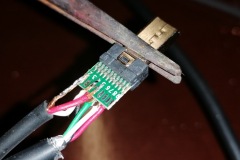
Soldering the two cables to the tiny solder pads requires a steady hand and experience in soldering. The USB as well as the audio cables have quite thin wires (AWG26 to AWG28, which equals to 0.12 mm² to 0.08 mm²), except the USB power wires (AWG22 or AWG24 in quick charge cables, which equals to 0.32 mm² and 0.20 mm²). The wires are rather stiff. Therefore, aligning the wires to the solder pads may be tricky. It gets especially tricky, if the wires are exposed from the outer isolation for less than a centimeter.
Advice: Always check the finished cable for shorts and proper contact with a multimeter!

Soldered Multiport adapter with USB (bottom) and headphone (top) cables

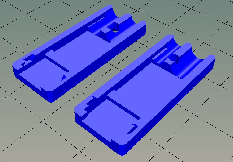
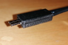
To reduce wear, which may lead to wires breaking off the solder pads, I designed a connector housing / case. The housing holds the adapter as well as the cables in place. Furthermore, this is the only proper way to handle the connector upon pluggin to / unpluggin from the camera.
The connector case is 3D printed. I share the STL file on Thingiverse here:
https://www.thingiverse.com/thing:4279366

Multiport adapter case – 3D model in 2 parts

Disclaimer:
This is a guide put together as reference for me. If you follow this description, you will do so on your own risk. I may not be held responsible for any damage or injury caused!

Battery replacement of Panasonic hair trimmer, Models ER1410 and similar with standard AA NiMH batteries

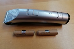
I own a Panasonic ER1410 hair trimmer. Unfortunately, after a few years of service, the batteries did no longer charge. I continued to use it in wired mode. But it is by far no comfort to have the cable dangling around. So after some time I decided to check for a battery replacement.
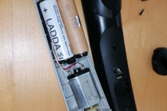
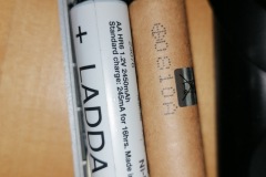
There are several offers for a set of replacement batteries available online. But these are quite expensive. Luckily the batteries are NiMH rechargable ones in AA / Mignon size. The only difference from the standard AA batteries is a pin like connector on both poles, which slide in a metal groove for contact. The design is replacement-friendly, as the batteries are not soldered to the PCB. Instead, there is a 2 slot battery carrier, designed for the pin like connectors.
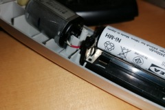
When a standard AA rechargable battery is inserted to the battery carrier, the battery has not quite good contact. To fix this, use a set of pliers to bend the metal contacts a bit. The batteries will have sufficient contact and the hair trimmer will work well!

Here are the steps I had to follow:
1. remove trimmer cartrige
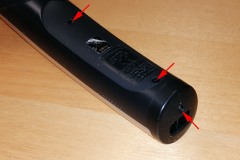
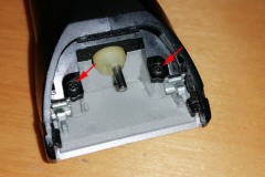
2. unscrew all 5 screws (see photo for positions)
3. remove black round part at charger connector
4. lift black bottom part
5. remove batteries and remember polarities!
6. bend metal contacts inwards with pliers until new batteries have firm contact
7. insert new 1.2V NiMH AA batteries (check polarity!)
8. close trimmer and fasten all 5 screws
9. test operation and charging

Disclaimer:
This is a guide put together as reference for me. If you follow this description, you will do so on your own risk. I will not be held responsible for any damage or injury caused by a DIY repair. Be aware, that using wrong batteries (i.e. non-rechargable, wrong type / Voltage, …) or batteries installed wrong may cause serious injuries and carry a high risk of fire!

Dark Sky Logger – my extended DIY Sky Quality Meter

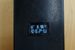
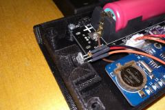
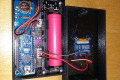
A few weeks back I had the DIY Sky Quality Meter demo setup working (see here). My primary target in building a Sky Quality Meter was to have a complete all-in-one ambient conditions logging device. So to finalize this project, I added a micro SD-Card reader, real-time clock, barometric pressure sensor and a rechargeable battery. I could manage to squeeze all the code into an Arduino nano :-). With the small footprint of the Arduino nano, I could build a case box (3D-printed) with only 123x68x34mm external dimensions.

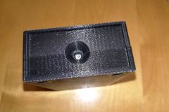
One essential part of the case is a chamber for the TAOS TSL237S sensor. The status LEDs of the Arduino did alter darkness readings severely. So any light apart from the night sky has to be shielded from the sensor!
Furthermore, the sensor requires a IR-block and color correction filter, to work comparable to the Unihedron Sky Quality Meter. As described here, Unihedron uses a HOYA CM-500 filter. I could find an almost identical filter, which is now included in the case as front cover of the sensor chamber.

My Arduino code may lack some fine tuning (forgive me, but I will not publish my source code. It would not be fair to Unihedron, who had all the development to build the original SQM device!). But the sensor readings are comparable to the second fraction digit in most cases to the SQM unit I could use for testing. This is sufficiently precise to me. I do refresh all the values (darkness, sensor frequency reading, temperature, humidity, pressure, dew point, calculated altitude, battery voltage, presence of SD card as well as time and date) every 5 seconds. This is someway insane, as a refresh rate of 30 to 60 seconds would still be very high 😉

With a freshly charged 18650 battery, my device may record for more than 50 hours. So even a weekend trip would be no issue.

For all curious folks out there, this is the parts list:
– Arduino nano v3
– DS1307 RTC module
– BME280 – temperature, humidity and pressure module
– Micro-SD Card interface
– 1.3″ OLED Display (128×64 Pixel)
– 18650 Lithium battery carrier with charger and 5V output
– TAOS TSL237S sensor
– 8mm UV-IR Cut filter
– 3D printed case

And this is the device:

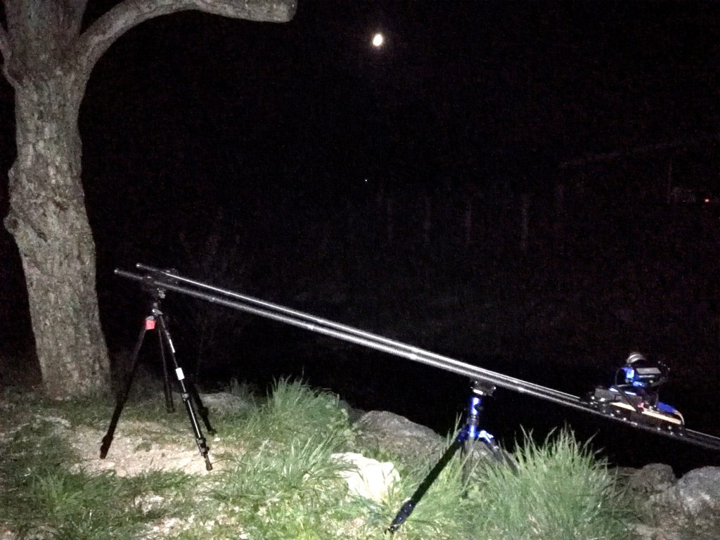
Camera slider – night shot with inclined setup

After finishing the slider, I was eager to test the whole thing. To test the capabilities, I went for an inclined setup with 3,5m length and 1m height difference. Well, the footage proofs a good overall performance. But unfortunately the motor is not strong enough to drive the slider cart all too well uphill. OK. The motor is without reduction gear and the motor may drive the slider cart at up to 1,2m/s… So for inclined setups, I have to add a reduction gear / worm gear drive or counter-weight system…

Sequence 1: 10s exposures, going up. Slider stalls due to overload

Sequence 2: 1s exposures at high ISO (it was too late in the night 😉 ), going down

poor quality photo of the setup

Camera slider – build complete :-)

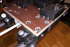
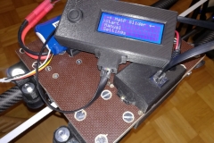
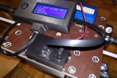
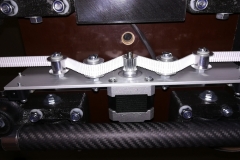
After several hours of designing, 3d printing, drilling, soldering and assembling, my camera slider is ready to use! All components are neatly packed within cases, so that the only wires visible are the power supply from the LiPo battery pack and the shutter release cable to the camera. I have several extensions in mind, like a pan-tilt unit. But for the moment, I will test and use the setup as is. The next improvements will be more on the firmware, for more features: non-linear movement, slow start, slow finish, pre-defined profiles, … for more impressive movies.


Now, concluding the build, I have the following parts in the final setup:

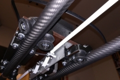
  •  12 U-groove wheels, matching the carbon fiber tubes (3D printed plus ball bearings)
  • 4 wheel carriages, each holding 3 U-groove wheels (3D printed)
  • 1 case for the microcontroller and motor driver (3D printed)
  • 1 case for shutter release, power supply and connectors (3D printed)
  • 1 hand-controller case (3D printed)
  • 1 battery bracket (3D printed)
  • 2 end-assemblies (5 parts each, 3D printed)
  • 2 supports (3 parts each, 3D printed)
  • 1 NEMA17 stepper motor
  • 1 A4988 stepper motor driver
  • 1 Arduino Nano (Atmel 328 microcontroller)
  • 1 4×20 LCD
  • 1 Joystick module
  • 1 DC-DC converter
  • 2 micro switches with long lever as end switches
  • GT2 10mm timing belt with wire reinforcement
  • 1 GT2 10mm 20 teeth pulley wheel
  • 4 GT2 10mm idler wheels
  • A whole bunch of M3 to M6 screws and nuts
  • 40x3mm flat aluminium
  • 30x50x3mm L-shaped aluminium
  • carbon fiber tubes

The project was really a fun to make. Even more, the resulting slider provides flexibility and transportability! I may configure the slider in any length, depending on the available tubes. The tubes I use, are 37cm in length and have aluminium screw-in adapters to fit one to the other. I have a bag, which I used as personal item in air travel. The bag holds the complete setup for up to 5 meters (exkluding tripods). The bag weighs in at approximately 5kg – so it is a light weight setup for the length possible.

This site uses cookies. By continuing to use the site (including navigation and scrolling), you agree to the use of cookies. more information

The cookie settings on this website are set to "allow cookies" to give you the best browsing experience possible. If you continue to use this website without changing your cookie settings or you click "Accept" below then you are consenting to this.

Close