Damascus knife – building the handle

A few weeks ago, I built a damaskus knife blade (see Damascus knive workshop). Now I finally had time to build the handle. Part of the delay accounted for the decision in material and design of the handle. After some serious research and window shopping, I found the perfect combination I would love to have: desert iron wood and silver.
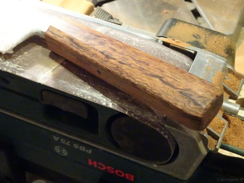
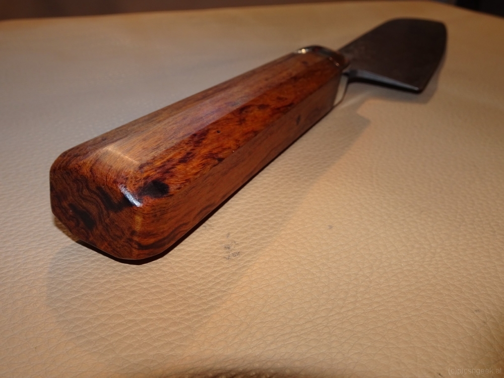
Desert iron wood is a very dense and hard wood. The core parts have a deep red color with wonderful dark texture. But it is not at all easy to find a piece at reasonable prices. Luckily I found an online store, offering a block of desert iron wood with matching size and texture to my likings.
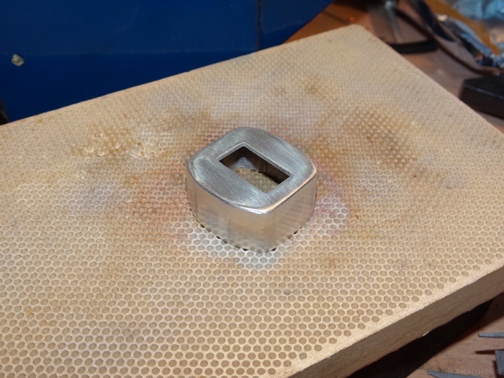
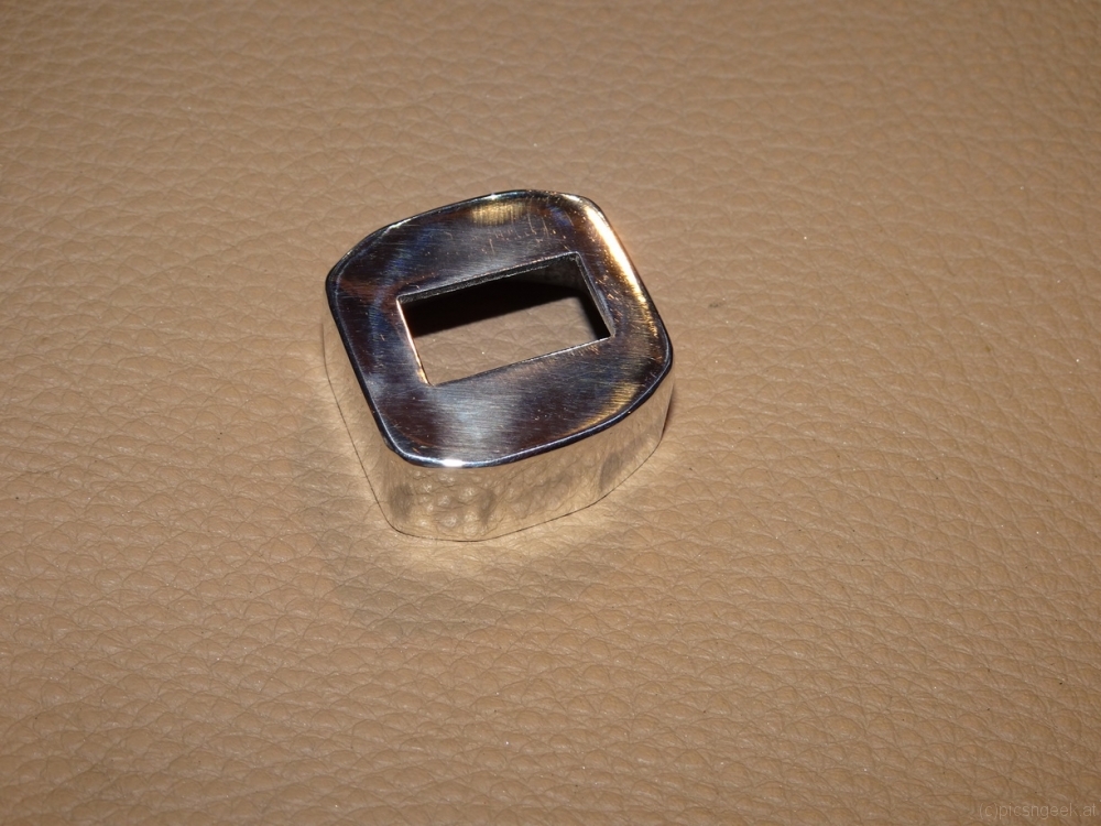
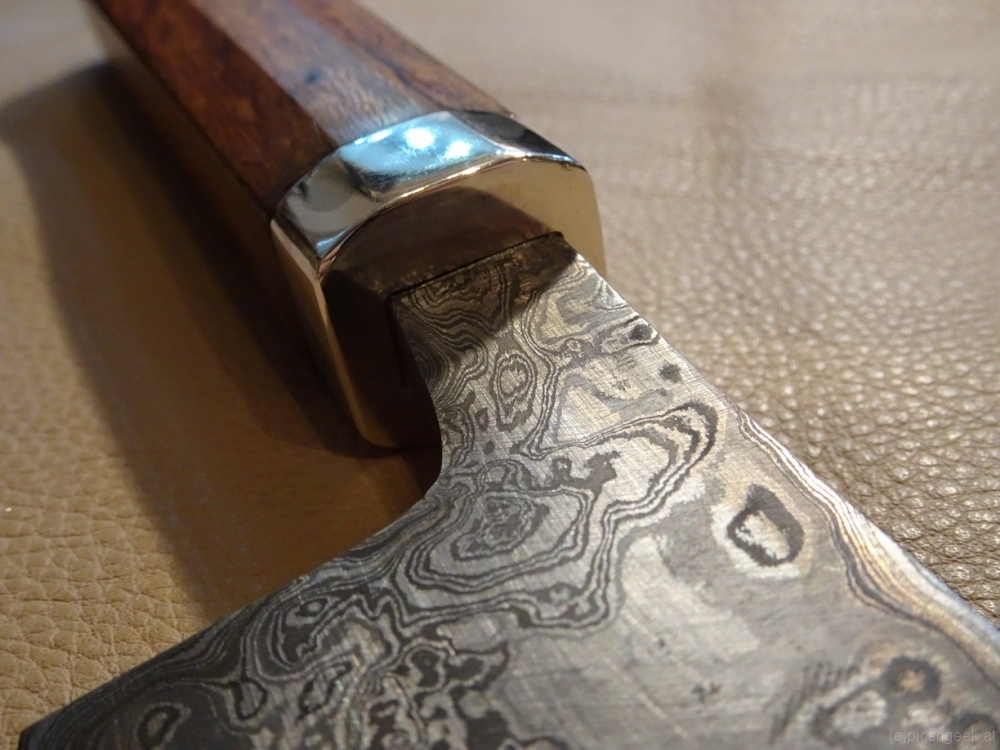
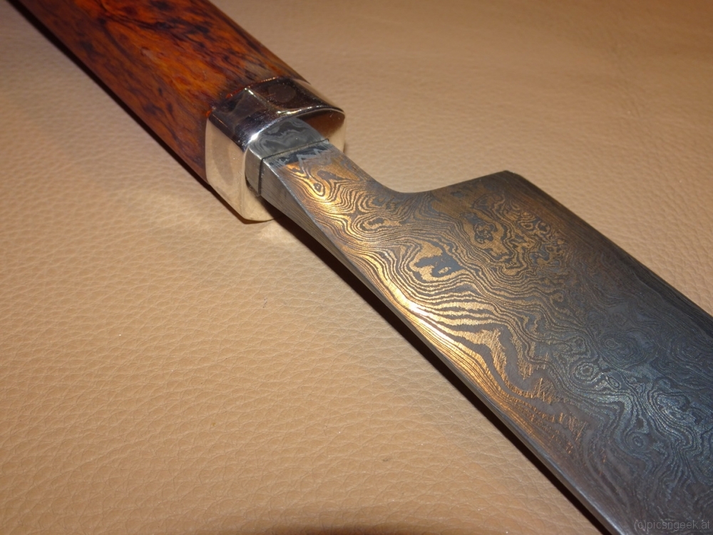
The bolster shall be like a cap, continuing the shape of the handle. As a material I use sterling silver.

The shape of the handle should become rather minimalistic. Further more, I wanted to have some resemblance to traditional Japanese handles. Therefore I chose a prolongued octagonal shape, which gradually gains a bit in height from the bolster to the end.

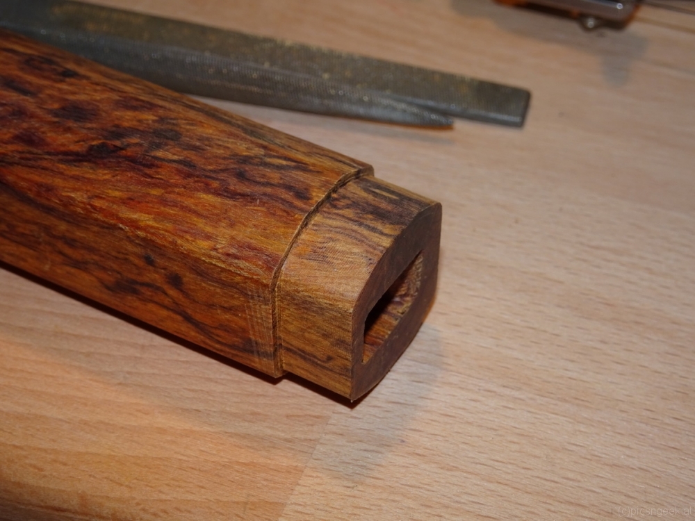
To build the handle, I started with the wood. I drilled a hole at the exact position to center the blade. Then I used small files to match the hole with the tang, which has a rectangular shape and is a bit off-centered to the rest of the blade. This was really time consuming, as the desert iron wood clogged the files within a few strokes. But finally, after a few hours of work, I had a perfect fit for the tang. I let approximately 5mm of the tang still protruding the handle, to have more strength in the final assembly by hammering the handle on to the blade.
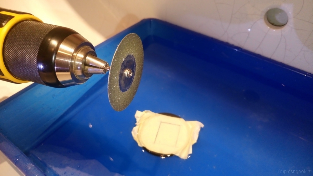
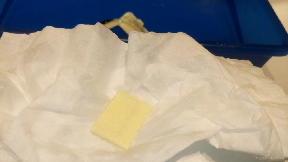
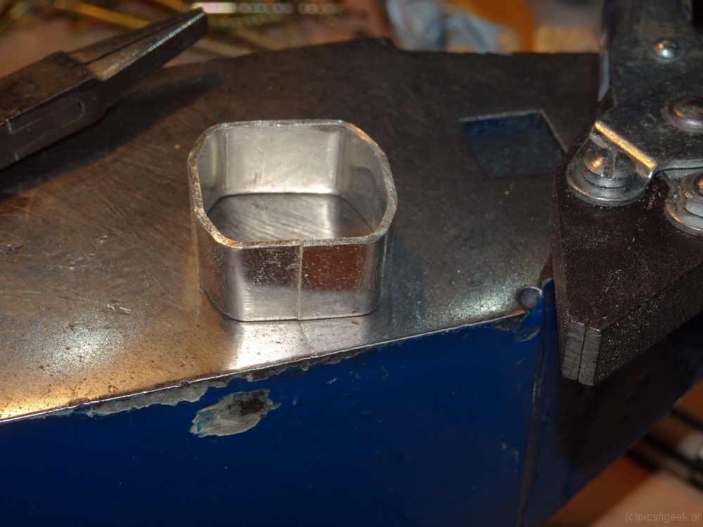
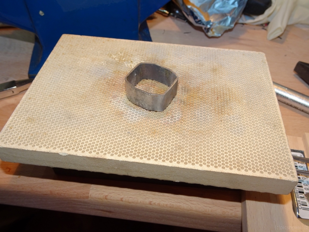
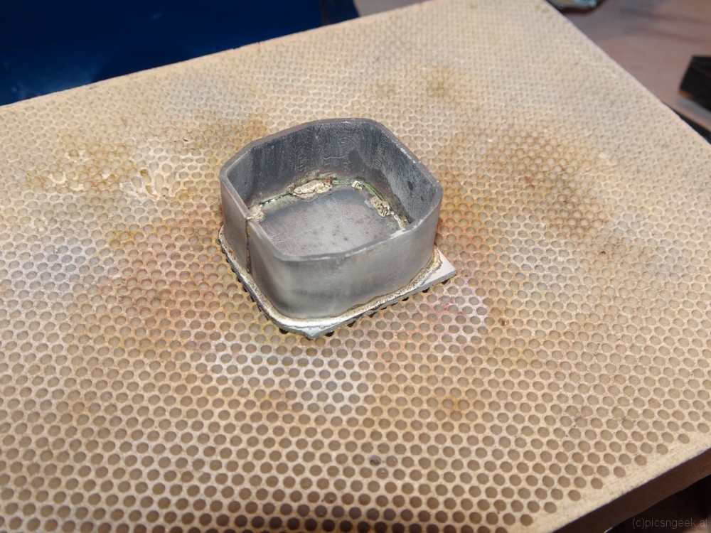
The next step was to make the recessed front, where the bolster will fit in. I cut a line at exactly 10mm from the front edge. Then I filed away 1mm of wood, as I will use 1mm sheet sterling silver. From a strip of 11mm width I formed a ring with an octagonal shape matching the handle, using parallel pliers. The ring is soldered with hard sterling silver solder. After filing and sanding the edges to have perfectly flat sides, I cut a sheet of silver with a bit of excess border. The ring is soldered to the sheet, again using hard solder. After cleaning and filing away the excess material, I could drill and file the hole for the tang. This again was a bit time consuming, to create a perfect fit…

Finally, I sanded and polished the silver bolster, gave the desert iron wood a last fine sanding. Then I mixed a bit of epoxy with desert iron wood file dust. I added glue to the bolster and into the hole for the tang. So I would have a really strong bonding betreen all the parts. I hammered the bolster to the handle (which was only necessary for the final 2mm). Following immediately I inserted the knifes tang to the handle. Using a rubber hammer, I pushed the tang into the final position within the handle.
Meanwhile I set an oven to approximately 70° Celsius for increased strentgh and faster hardening of the epoxy. After cleaning away any excess epoxy with acetone, I set the whole knife in the oven for curing.

Hint: If there is any epoxy pushed out of the joints during curing, you may use a small soldering iron to work the exopy off the surface. The remaining thin film of epoxy may be removed with acetone. If you are careful, you will most likely have a scratch free surface afterwards!

The last thing to do is a thin coating of hard oil.
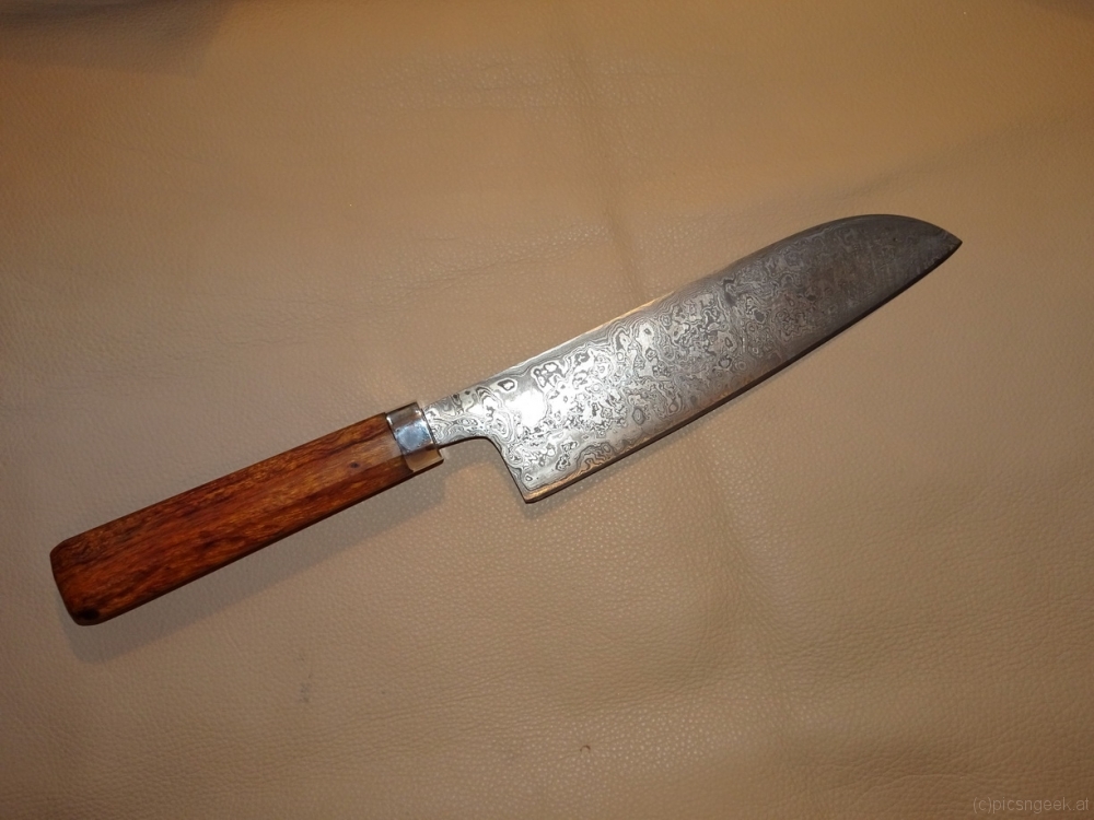
After more than 20 hours of work (including forging the blade), the knife is ready 🙂 The final result is a perfectly balanced knife due to the heavy wood handle. The center of balance lies exatly in front of the bolster. The blade will hopefully last for a very long time and provide perfect cuts due to approximately 56-58 HRC.

Motorized camera slider

For quite some time I would like to create night time movies in hyperlapses. For me, the most stunning results may be created by moving the camera along a linear path by the use of motorized sliders. Motorized sliders, which are more than 2 meters long, have an impressive price tag. Further more, these tools are bulky and heavy, especially when the setup attached to weighs in a few kilos.
Therefore I decided to build my own with a few goals in mind:

  • light weight
  • portable
  • variable length
  • suitable for a load of a few kilos
  • wider range of speeds
  • extendable for rotation axis
  • direct control for camera(s)

To achieve all or most of these goals, I came up with a design built around carbon fiber tubes with aluminum screw-in fixtures. Appropriate tubes may be built from scratch or are readily available for camera gimbals. I chose the camera gimbal extensions, as there is no big price difference to buying stock material. Further more, they come in a handy size of +/- 40cm in length.
The end supports will have to hold the tubes as well as a gear belt, along which the slider cart will be driven. For long setups, I created supports, to prevent bending and excessive stress to the tubes. Both types of support will have legs as well as tripod mount screw holes (3/8 UNC thread)
The slider cart consists of 4 blocks holding 3 pulley wheels each. The blocks are attached to a base plate (in test setup a plywood sheet). In the middle of the base plate lies the motor unit consisting of a steper motor and 4 guiding wheels to create enough tension for the gear belt to be driven by the motor.

All in all, the shopping list is really limited, as most parts were 3D-printed. What I had to purchase or use (most parts were already to be found in the workshop) was:

  • carbon fiber rods (at least 8)
  • 24 ball bearings type 626 2RS (6x19x6 mm)
  • GT2x10mm belt matching the desired length
  • GT2 20 tooth drive gear
  • 4 guide wheels without teeth for 10mm belt
  • 1 NEMA 14 stepper motor, <3V nominal voltage
  • several M5 and M6 screws, washers and nuts
  • 3/8 UNC thread taper
  • approximately 0.5m of 40x3mm Aluminum sheet
  • 25cm of 30x50x3mm Aluminum L shaped profile
  • Arduino, Stepper motor controller like A4988, 12-18V (lithium) battery
  • 1 can of rubber spray like Plasti-Dip (c)

Most of the time I spent was in CAD constructing the parts. Printing took about 3 days. The pulley wheels have to be sanded for a smooth surface before coating with rubber. The remaining time was spent in cutting, drilling and tapering the aluminum parts, before all parts could be attached together.

The first test run was more than pleasing. See for yourself:

The next thing to do is to create a control box with all the features implemented for every day use 🙂

Wooden tripod base for small telesope mounts

DSC_0456

Picture 1 of 5

Several years ago I purchased my first telescope. The telescope had an EQ2 mount included. The EQ2 is an entry level mount, with an all in one mount and tripod base. The EQ2 served me for some time, until I got frustrated with the instability and bad and worn gears in my unit. So one day I replaced it with a goto mount. The last time I used it was for the 2006 solar eclipse in Turkey. Since then the whole thing had to sit and wait for a long time in the basement.
Several years passed until I added a Sky-Watcher Star Adventurer to my collection of gear (I am really happy with this little travel mount!). To use the Star Adventurer in its full extent, a sturdy tripod is required.
None of my photo tripods (neither aluminium nor carbon fiber) could provide a rigid platform to hold against the vibrations of wind or camera mirror flip. After reading several comments on tripods for the Star Adventurer, the direction was obvious to use a wooden tripod. I was already scanning the market for proper tripods, when I remembered the EQ2, which had quite a nice wooden tripod. The only problem to solve was, to replace the EQ2 head with a flat base. The base should provide a stable means to attach the Star Adventurer with one UNC 3/8 screw…

The design was straight forward: The construction exists of 2 parts. A 3-prongue base to attach to the tripod legs and a raised platform for the Star Adventurer. As I didn’t have a large enough piece of beech wood for the base, I used a 40mmx40mm beech wood block. The block was cut in 3 equal parts. These are mitered at 60°. On the other side, I rounded the top part (a rather aestetical finish) and drilled the hole for the bolt attaching the tripod leg.
The platform consists of one round disc of 40mm thick beech wood, which I cut out with a 100mm circular drill. The 4 parts were then glued together with 2 wooden pins joining each leg part, to enhance mechanical strength.
After drilling the required hole for the UNC 3/8 screw and the recessed hole for the screw head with washer, the whole part was sanded, cleaned and finished with hard oil. The platform top face received a rubber coating for a better hold of the Star Adventurer.

Parts used:
3x 40x40x100mm beech wood
1x 100x100x40mm beech wood (for platform)
6x 6mm wooden dowel

IR or Full-Spectrum modification of a Sony Alpha 6000 camera

For quite a while I was looking for a camera, capable of better capturing the 656nm light of the H-alpha emissions from deep sky objects like gas nebulae or the suns prominences. Further more I was curious about infra red daylight photography. First, I thought I should buy an astronomy camera with very low noise due to active cooling. Unfortunately, such cameras are with a reasonable price tag. Further more, the astronomical cameras require an external power supply as well as a computer for control and data acquisition. Having such a camera would therefore only be reasonable, when I would spend several nights each month to capture images.

Then I thought, there are several regular DLSR cameras available (directly or by modification) which are capable of infrared or even full spectrum photography. These cameras or the modifications are available at attractive prices. Further more, the camera would be compact, easy to handle and suitable during daytime as well. There are 2 drawbacks in deep sky photography, which only really become relevant, when capturing very faint and distant objects at higher ambient temperatures:

  1. no active cooling
    the camera has a higher thermal noise. To compensate for this, more images have to be captured
  2. less color or black and white resolution
    Astronomical cameras usually have 16 Bits per channel, DSLRs have 12-14 Bits per channel. This is 4 to 16 times less detail, which is not so much of a problem, when capturing brighter objects

The modifications would imply to change the IR filter, which is attached in front of the imaging sensor. The whole procedure requires a service manual or a detailed description of how to disassemble the camera of choice. Fortunately I came across a very detailed step by step description of the disassembly process of the Sony Alpha 6000 camera. The description is (until now) available here from the company Lifepixel. They are also offering conversion services if you are not up to the task. One of the biggest challenges is to cope with the rather delicate ribbon cables. Pay as much attention as possible when disconnecting and connecting these cables! Further more, pay attention to the position of the On-Off power switch! If you change the position before reassembling, you may break the switch or the ribbon cable the switch sits on. If you do break this switch you are in serious trouble!

A hint for organization: During the modification process, one has to remove a whole lot of screws in different shapes and sizes. To keep all the screws and parts organized, I printed the complete step by step instructions with two steps per page (side by side). on the bottom of each page I attached a strip of masking tape, with the sticky side up. So I could place all the screws in the corresponding positions below each steps photo. Et voila! All parts are kept where they should be and matching the sequence.

Hint concerning electronics: You are dealing with highly sensitive electronic parts! You will create enough electrical charge to destroy the electronics when you move around! Use wrist band grounding wires and static precautions when operating with such sensitive devices!

Cutting filter glass for camera IR or full spectrum modification

Upon preparations for my Sony A6000 camera full spectrum modification, I didn’t find any reasonably priced IR-filter replacement. Most of the offerings I found have been way above any reasonable price. So I decided to try cutting my filter replacement myself…

I did some research on cutting filter glass. Most of the guides I found used window glass cutters to score and break the glass apart. This technique is in my opinion perfect with most ordinary glasses. Though filter glass, which is hardened and coated does not break evenly. You seem to get very rough edges, which would not be in acceptable tolerances for me. Cutting a larger piece and grinding down to desired size would be the only option with this method.
An other method I found for cutting glass (in general) was, to use diamond plated cutting wheels. All the results I have seen, provided nice cuts. So this should be the technique to go for…

I previousely did use 1 inch diameter diamond cutting wheels on several occations. But for cutting a nice and clean line, I purchased a set of 50mm diamond plated cutting wheels with less than a millimeter thickness. These were available online for less than 10 EUR.

Preparations and cutting:

The easiest way to mark the outline of the desired filter is, to stick a strip of masking tape on both sides of the filter. This has two benefits:
1) you can easily mark the lines with a pencil or waterproof pen
2) the surface of the filter is protected against scratches and durst

Now research the dimensions required and draw the rectangle on the tape. When you are done, go to your sink, take a medium sized flat container and fill it with water to approximately 1 cm level. Attach the cutting wheel to a battery powered electric drill (water + electricity is too dangerous!!!)
Use a very low speed to turn the cutting wheel. Now dip the filter in the water and bring it with very low pressure to the cutting wheel. Cut all four edthes from one corner to the other. Cutting is impressively easy and fast. Results are absolutely pleasing 🙂

Clearing a stuck zoom lens in a Panasonic Lumix DMC-TZ20 camera

A friend of mine asked whether I would repair their camera. After dropping the camera, the zoom did block operation. After switching on the camera, the zoom tried to extend. Though as the soom got stuck somewhere in between, the camera retracted the lens and switched to error mode.
I agreed to do my best to restore operation. Unfortunately this task got more challenging as I expected:


I had to fully disassemble the camera, to reach the zoom barrels. The zoom barrels (made of plastic) have a sophisticated set of guides to operate the lens. That said, the pattern set up defines the movement of the front and center lens assembly, to focus and / or zoom. By dropping the camera, one of the tiny guide pins got pushed to the wrong aisle. So the camera could not move the lenses and barrels freely. As most of these cameras detect an overload, and the Lumix DMC-TZ20 does this as well, the camera retracts the lens for protection and sets error mode.
By repositioning the barrels and lense assembly (which was not at all an easy task), the camera could return to normal operation!

Questions? Leave me a note! I will try to help 😉

Modify the characteristics of propane gas torches

I was challenged by the need of more thermal power of one of my propane torches to melt higher quantities of metal. Furthermore, I needed to modify the characteristics of the flame, to have a neutral flame to perfectly balance the available oxigen levels as well as carbon levels around molten metal.

The first change was quite straight forward: To increase the possible thermal output of the torch, higher volume of gas has to pass through the nozzle. My nozzle had a 0.5mm hole for the gas to exit. So enlarging the size by drilling a 0.55mm hole was – apart from the rather delicate work – not so much of an issue.

The second change required to modify the air flow. My nozzles generated a somewhat carburizing flame. Therefore the available oxigen was a bit too low. When higher amounts of air may be sucked in by the gas travelling through the nozzle, the flame gets more reduzing. So I opened the air holes by small amounts from each test to the next, until my desired flame characteristics was met…

This site uses cookies. By continuing to use the site (including navigation and scrolling), you agree to the use of cookies. more information

The cookie settings on this website are set to "allow cookies" to give you the best browsing experience possible. If you continue to use this website without changing your cookie settings or you click "Accept" below then you are consenting to this.

Close