SkyWatcher pier extension- a major design flaw?

I like to observe or image through my 10 inch Newtonian and 102mm APO telescopes. Both have quite long tubes. When slewing to high altitude objects, you risk to collide with the tripod legs. There is only one way to avoid such situations. You have to raise the mount head from the tripod by means of pier extensions. When ordering an off-the-shelf pier extension, one would assume, it would be designed properly and provide a solid construction. With the SkyWatcher pier extension I was proven wrong – unfortunately. Here is why:

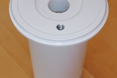
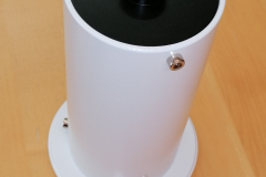
A few days ago I received the SkyWatcher pier extension I intended to use with my AZ-EQ6 mount. The pier extension basically consists of 3 parts:
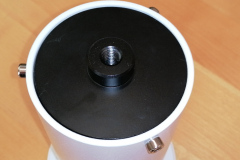
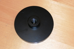
– A black base plate, connecting to the tripod
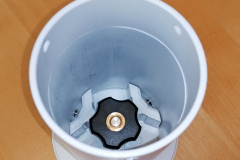
– A “pipe” like part with white finish
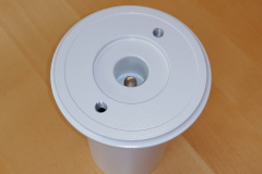
– A top mounting plate, where your mount will be attached.
To attach the pier extension, one has to remove the Azimuth bolt from the tripod first. The Azimuth bolt has to be attached to the top mounting plate for fine adjusting the mount head.
Next, one has to unscrew the 3 locking screws of the black or white base plate. Either one is OK, but with the white top plate it is easier to place the mount on top. The top mounting plate includes the M10 threaded rod with knurled wheel to attach the mount to. You have to securely tighten the M10 bolt to the mount, as you will not be able to tighten it more, once it is all set up. Finally, you place the mount head on top of the base plate / base plate plus extension (if you unscrewed the top plate alone) and add and tighten the locking screws.

Now that the mount is set up, you will soon discover the design flaws I refer to:

  1. pier extension is not stiff enough
    As the pier extension consists of 3 parts, which are held in place by M4 screws, you don’t get a solid built like when the parts would have been welded together. As I have seen with other comparable products, an opening to one side would have provided access to the M10 bolt with a rock solid quality.
    A combination of AZ-EQ6 and 10 inch Newtonian is far too much! A small(er) scope and mount might be OK though.
  2. No Azimuth locking bolt on the base plate
    This is a show-stopper to me! The whole setup from the tripot up to the scope turns on the slightes touch to the telescope! Any polar alignment will be lost upon changing eyepieces or the like!

I considered, drilling a hole to the base plate to add an azimuth bolt. Though as the whole thing was not stiff enough, I returned the pier extension (thank you Teleskop-Express for accepting a no questions return!).
If SkyWatcher would re-design this pier extension or release one with significantly improved design, I would immediately buy one. But up to this point, I have to avoid high altitude objects (or use a smaller telescope)…

Skywatcher AZ-EQ6 stalls during Go-To – Power supply issues

Earlier this year I got a lucky owner of a 10 inch carbon fiber newtonian telescope. The scope weighs in around 13kg. So I thought, this would fit perfectly within the capabilities of my AZ-EQ6 mount. Well, yes, by numbers (the AZ-EQ6 payload is 20kg), but not in my setup.
First of all, I had to add a third counter weight on the extension bar. So an overall counter weight of 15kg has to be added for these big scopes. Second, the mount became unreliable, as in Go-To movements, the mount stalled at some instances with a squeaking noise.
The noise is easily identified as the stepper motors skipping steps and not being able to drive the mount to the desired position. The mount won’t be harmed in any way. But the alignment will be gone for good. So you have to reset the mount and align with the sky again. Or, if this happens during alignment, you won’t be able to tell or teach the mount the actual sky model.

Additional information: Why do stepper motors skip steps?
A stepper motor, as built into the AZ-EQ6, consists of 2 static coils and a geared permanent magnet on the rotor. When the coils are powered in the right pattern, the generated magnetic field causes the rotor to move (in most cases 1.8° per full step). These coils are loaded in forward and reverse alternately. During the loading phase of a coil, the coil poses a resistance. This resistance limits the current. The possible current combined with a given voltage (supply voltage) defines the available power to load the coil and generate the magnetic field to move the rotor. How strong the magnetic field has to be is set by the inertia of the motor itself, the desired speed and the attached load. Loading the coil takes a bit of time (in the range of 100 microseconds to a few milliseconds). To achieve the desired movement (mechanical work in given time), a certain minimum of voltage, current and load time has to be provided.
If at least one of the parameters does not meet the requirements, the motor will not be able to fulfill the movement. So the stepper motor will not fully move to the next step “position”. When the motor controller begins to change the supply pattern of the coils before the rotor reaches a sufficient angle towards the next step position, the rotor might be pulled back towards the previous matching position. So the rotor will be trapped in a narrow range of steps, jumping back and forth.

I was driving the mount with a 12V 20A power supply at home. When on the mountain top, I used a 12V sealed lead acid gel battery. All was fine, using scopes with less than 10kg (and only 2 counter weigth discs). But with the 13kg scope and extra 5kg counter weight, I added too much inertia to the drive system. So, as I want to use the 10 inch scope with the AZ-EQ6, and the AZ-EQ6 has no option to reduce Go-To speed, there is only one option to improve the setup: increase the voltage!
The manual says, Input Voltage: 11-16V DC, 4A. I tested the mount with a lab power supply at 15V. The mount was happy with the provided power. Further more, all Go-To movements completed without and problem! Sollution found!
For home use, I could find a quite cheap 15V 4A supply (15V supplies are easier to find than 16V supplies). For mobile use, there is no reasonable power pack, providing 15V. So I purchased a powerful 120W DC-DC boost converter from 12V up to 15V, which will run from car- or other 12V battery. (This is a temporary setup, until my mobile lithium battery based astro power supply is ready to use)
Both supplies got their GX12-2 connector to be plugged in to the AZ-EQ6 supply terminal…

This site uses cookies. By continuing to use the site (including navigation and scrolling), you agree to the use of cookies. more information

The cookie settings on this website are set to "allow cookies" to give you the best browsing experience possible. If you continue to use this website without changing your cookie settings or you click "Accept" below then you are consenting to this.

Close