Prominence timelapse from 2020-11-22

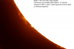
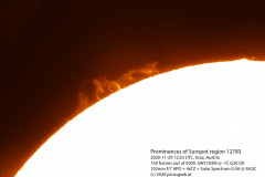
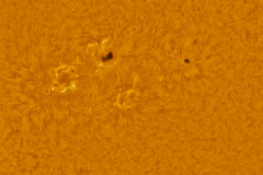
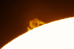
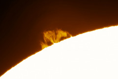
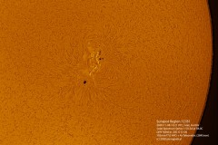
On November 22 on the south-eastern limb of the sun, a stable prominence was visible. The prominence seems to consist of three different prominences (one flame type, one fan type and one arch type). They all seem to origin from sunspots 12785 and 12786. Whereas I assume, that the arch type prominence to the right is most likely from 12786.

The timelapse shows the activity of the prominences from 09:45-12:30 UTC. The clip has 342 individual images. Each image was stacked from 12 frames out of bursts of 300 frames. Post processing and colorization in PixInsight.

These 2 images from beginning and end of sequence show the beautiful structur as well as the changes within.

150 Megapixel mosaic of the sun

My solar imaging setup has a quite high magnification. Even though I use a 20 Megapixel QHY183 camera, I may only frame less than a third of the disk diameter at once. This is really neat for prominences and sunspots. But I may not record the whole solar disk. Therefore my only way to go is a panorama or mosaic.

The tricky part of recording a mosaic of the sun is, that you don’t have too much time to complete. First, the sun rotates (even the 25 days period may cause defects at high resolution imaging). Second, some features like granulation or prominences may change within minutes.
For high quality results, the lucky imaging approach has to be used. Meaning, each individual recording for a tile should consist of as many images (lets call them frames, as the data is recorded as a video) as possible. In post processing, only the best frames will be selected and combined for low noise results.

Last weekend I ran the first real test for a giant mosaic image of the sun in H-alpha. I recorded each individual tile with SharpCap. I had to use the seeing filter due to a rather slow USB connected drive. Each tile consists of a set of only 100 out of 2000. From these 100 selected images, only 4 were used to create the final image tiles (which proofed to be a wrong decision, as noise levels remained quite high).

To record the complete surface, I needed to capture 12 tiles. So I ended up using 48 individual frames out of 24.000. After crunching through the 30+GB of data recorded on disk (which was only 5% of the images captured) for several hours, I finally have a stunning picture of the sun in high resolution 🙂

Processing steps:
1) Stacking in AutoStakkert!3
2) Stitching in Photoshop (manually, as neither Photoshop, nor Hugin were able to align the tiles)
3) Gradient removal in Photoshop
4) Wavelet sharpening in PixInsight
5) Histogram optimization in PixInsight
6) Cleaning of edges and border of image in Photoshop
7) Colorization in Photoshop

If you want to fully enjoy this image, here is the 7500×7500 pixel version.
Satellite transits Mars

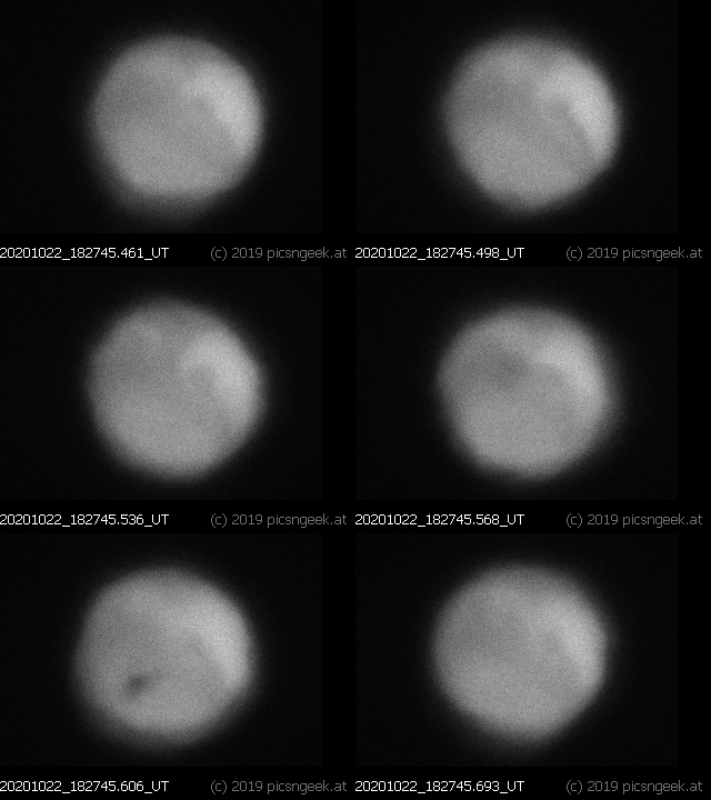
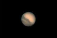
On Thursday 2020-10-22 in the evening, I captured image sequences of Mars (see seperate post). During one of the infrared test sequences (I wanted to compare noise levels at +2C vs. -20C) I saw a brief dark shadow passing the disk of Mars. First out, I thought it might have been a bat. But later on, when I analyzed the video, I found out, that the shadow was a satellite transiting Mars 🙂

The transit started at 2020-10-22 18:27:45.498 UT. The satellite left the disk of Mars at 18:27:45.687. So the duration was a very brief 190 Milliseconds! As I recorded with 178 frames/second, I could capture 27 individual images of the transit.

I definitively was very lucky to have registered the shadow during capture time. Otherwise I would never have seen this event in post processing…

Optics used: 10″ f/5 Newton with 2.5x Barlow (effective focal length was 3125mm)
Recorded with IR-650nm pass filter on QHY183M camera at +2C with 178 fps

Comet C/2020 M3 ATLAS – Nucleus movement

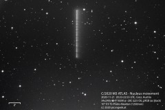
Saturday night (2020-11-21) I recorded LRGB data of comet C/2020 M3 ATLAS. Upon inspecting the image data, I detected a spinning movement of the comets nucleus. To show the movement, I combined the 34 individual LRGB images (240 seconds each) to one stack with the comet forming a curving trail.
During the course of 142 minutes, the comet moved 470 arcseconds (3.3 arcseconds per second).

Comet C2020 M3 ATLAS

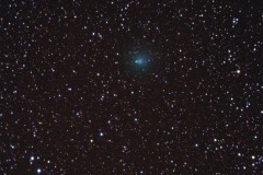
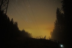
Last night I had to travel to Vienna. Fortunately I had to pass the eastern foothills of the Alps. As the motorway already went up to almost 1000m a.s.l, it was a 10 minutes detour to reach a dark place above the persistent and annoying fog layers (which are typically at 600 to 1200m a.s.l and quite frequent in autumn and winter).

I had packed my AZ-GTi travel mount, 72mm f6 APO and Sony A6400 as super lightweight and quick setup combo. I could capture almost half an hour of data, before the fog climbed up the hill. Unfortunately the amount of data was too low for good noise base. But anyway – as a first and quick result, it is very well pleasing 🙂

Moon meets Venus

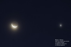
In the morning hours of October 14th, before dawn started to illuminate the sky, Moon and Venus were quite close next to each other. With a distance of 4 degrees and only 10% of the lunar surface illuminated, it was a beautiful sight!

Image captured with 200mm lens on tripod. No tracking. Minimal post processing with level adjustment and cropping.

Mars in opposition and (almost) all other planets

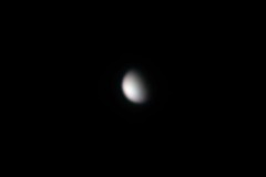
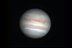
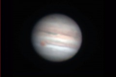
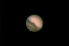
Finally, in the evening of 2020-10-08, there came a cloud free night with the moon rising not too early. Although the seeing conditions were not really faborable (high jet stream speed and rather bad layers), I had to go planet hunting.

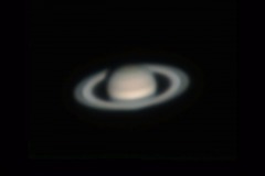
Jupiter and Saturn were rather low, but still well placed from my home location. Mars was already well up in the sky when night fell. Inbetween there were Neptune and Uranus. Both of them not quite spectacular with persisting seeing conditions.
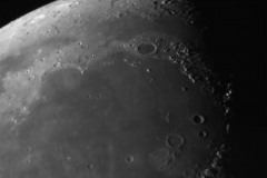
And finally I took a shot of the beautifully lit mountains on the Moon. The picture shows Montes Apenninus at the lower right, Montes Caucasus to the right (almost lost in the shadow) and Montes Alpes around Mare Imbrium. (North is up)

This time, I used my 10″ f/5 Newtonian with a 2.5x Barlow lens, to test oversampling capabilities. Well… The seeing conditions would rather call for no barlow at all, but I had to test the combo 🙂

All images are created from 4 separate, RGB+IR filtered video (SER) files with QHY183M camera. Each video consists of 500-10000 individual frames, from which 6-10% of the best were stacked.
The resulting resolution is 0.158 arc-seconds per pixel, which is a 3x oversampling of the 10″ scope (0.464 arc-seconds Dawes limit); Except the Moon, which is scaled to 33%

See the results processed AutoStakkert!3, Registax and Photoshop here:

SkyWatcher pier extension- a major design flaw?

I like to observe or image through my 10 inch Newtonian and 102mm APO telescopes. Both have quite long tubes. When slewing to high altitude objects, you risk to collide with the tripod legs. There is only one way to avoid such situations. You have to raise the mount head from the tripod by means of pier extensions. When ordering an off-the-shelf pier extension, one would assume, it would be designed properly and provide a solid construction. With the SkyWatcher pier extension I was proven wrong – unfortunately. Here is why:

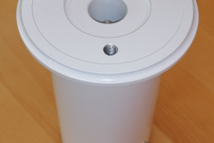
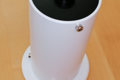
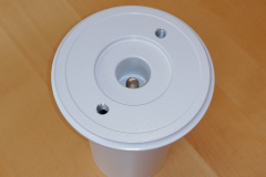
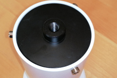
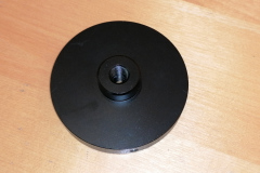
A few days ago I received the SkyWatcher pier extension I intended to use with my AZ-EQ6 mount. The pier extension basically consists of 3 parts:
– A black base plate, connecting to the tripod
– A “pipe” like part with white finish
– A top mounting plate, where your mount will be attached.
To attach the pier extension, one has to remove the Azimuth bolt from the tripod first. The Azimuth bolt has to be attached to the top mounting plate for fine adjusting the mount head.
Next, one has to unscrew the 3 locking screws of the black or white base plate. Either one is OK, but with the white top plate it is easier to place the mount on top. The top mounting plate includes the M10 threaded rod with knurled wheel to attach the mount to. You have to securely tighten the M10 bolt to the mount, as you will not be able to tighten it more, once it is all set up. Finally, you place the mount head on top of the base plate / base plate plus extension (if you unscrewed the top plate alone) and add and tighten the locking screws.

Now that the mount is set up, you will soon discover the design flaws I refer to:

  1. pier extension is not stiff enough
    As the pier extension consists of 3 parts, which are held in place by M4 screws, you don’t get a solid built like when the parts would have been welded together. As I have seen with other comparable products, an opening to one side would have provided access to the M10 bolt with a rock solid quality.
    A combination of AZ-EQ6 and 10 inch Newtonian is far too much! A small(er) scope and mount might be OK though.
  2. No Azimuth locking bolt on the base plate
    This is a show-stopper to me! The whole setup from the tripot up to the scope turns on the slightes touch to the telescope! Any polar alignment will be lost upon changing eyepieces or the like!

I considered, drilling a hole to the base plate to add an azimuth bolt. Though as the whole thing was not stiff enough, I returned the pier extension (thank you Teleskop-Express for accepting a no questions return!).
If SkyWatcher would re-design this pier extension or release one with significantly improved design, I would immediately buy one. But up to this point, I have to avoid high altitude objects (or use a smaller telescope)…

Skywatcher AZ-EQ6 stalls during Go-To – Power supply issues

Earlier this year I got a lucky owner of a 10 inch carbon fiber newtonian telescope. The scope weighs in around 13kg. So I thought, this would fit perfectly within the capabilities of my AZ-EQ6 mount. Well, yes, by numbers (the AZ-EQ6 payload is 20kg), but not in my setup.
First of all, I had to add a third counter weight on the extension bar. So an overall counter weight of 15kg has to be added for these big scopes. Second, the mount became unreliable, as in Go-To movements, the mount stalled at some instances with a squeaking noise.
The noise is easily identified as the stepper motors skipping steps and not being able to drive the mount to the desired position. The mount won’t be harmed in any way. But the alignment will be gone for good. So you have to reset the mount and align with the sky again. Or, if this happens during alignment, you won’t be able to tell or teach the mount the actual sky model.

Additional information: Why do stepper motors skip steps?
A stepper motor, as built into the AZ-EQ6, consists of 2 static coils and a geared permanent magnet on the rotor. When the coils are powered in the right pattern, the generated magnetic field causes the rotor to move (in most cases 1.8° per full step). These coils are loaded in forward and reverse alternately. During the loading phase of a coil, the coil poses a resistance. This resistance limits the current. The possible current combined with a given voltage (supply voltage) defines the available power to load the coil and generate the magnetic field to move the rotor. How strong the magnetic field has to be is set by the inertia of the motor itself, the desired speed and the attached load. Loading the coil takes a bit of time (in the range of 100 microseconds to a few milliseconds). To achieve the desired movement (mechanical work in given time), a certain minimum of voltage, current and load time has to be provided.
If at least one of the parameters does not meet the requirements, the motor will not be able to fulfill the movement. So the stepper motor will not fully move to the next step “position”. When the motor controller begins to change the supply pattern of the coils before the rotor reaches a sufficient angle towards the next step position, the rotor might be pulled back towards the previous matching position. So the rotor will be trapped in a narrow range of steps, jumping back and forth.

I was driving the mount with a 12V 20A power supply at home. When on the mountain top, I used a 12V sealed lead acid gel battery. All was fine, using scopes with less than 10kg (and only 2 counter weigth discs). But with the 13kg scope and extra 5kg counter weight, I added too much inertia to the drive system. So, as I want to use the 10 inch scope with the AZ-EQ6, and the AZ-EQ6 has no option to reduce Go-To speed, there is only one option to improve the setup: increase the voltage!
The manual says, Input Voltage: 11-16V DC, 4A. I tested the mount with a lab power supply at 15V. The mount was happy with the provided power. Further more, all Go-To movements completed without and problem! Sollution found!
For home use, I could find a quite cheap 15V 4A supply (15V supplies are easier to find than 16V supplies). For mobile use, there is no reasonable power pack, providing 15V. So I purchased a powerful 120W DC-DC boost converter from 12V up to 15V, which will run from car- or other 12V battery. (This is a temporary setup, until my mobile lithium battery based astro power supply is ready to use)
Both supplies got their GX12-2 connector to be plugged in to the AZ-EQ6 supply terminal…

This site uses cookies. By continuing to use the site (including navigation and scrolling), you agree to the use of cookies. more information

The cookie settings on this website are set to "allow cookies" to give you the best browsing experience possible. If you continue to use this website without changing your cookie settings or you click "Accept" below then you are consenting to this.

Close