Camera slider – build complete :-)

After several hours of designing, 3d printing, drilling, soldering and assembling, my camera slider is ready to use! All components are neatly packed within cases, so that the only wires visible are the power supply from the LiPo battery pack and the shutter release cable to the camera. I have several extensions in mind, like a pan-tilt unit. But for the moment, I will test and use the setup as is. The next improvements will be more on the firmware, for more features: non-linear movement, slow start, slow finish, pre-defined profiles, … for more impressive movies.


Now, concluding the build, I have the following parts in the final setup:

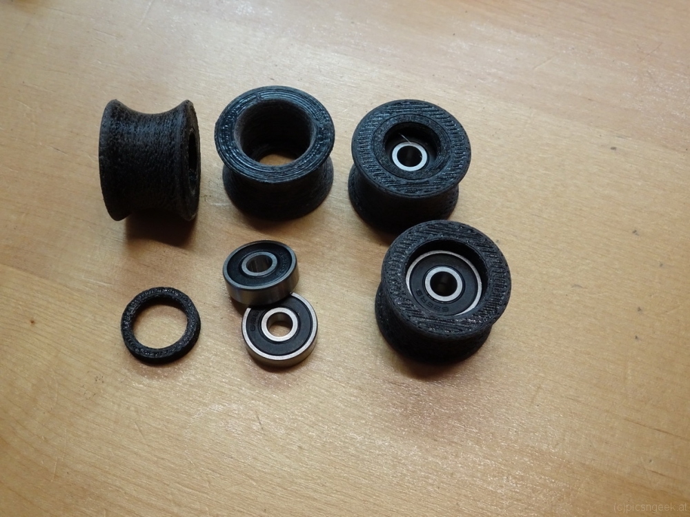
  •  12 U-groove wheels, matching the carbon fiber tubes (3D printed plus ball bearings)
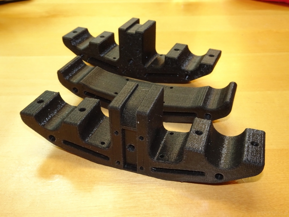
  • 4 wheel carriages, each holding 3 U-groove wheels (3D printed)
  • 1 case for the microcontroller and motor driver (3D printed)
  • 1 case for shutter release, power supply and connectors (3D printed)
  • 1 hand-controller case (3D printed)
  • 1 battery bracket (3D printed)
  • 2 end-assemblies (5 parts each, 3D printed)
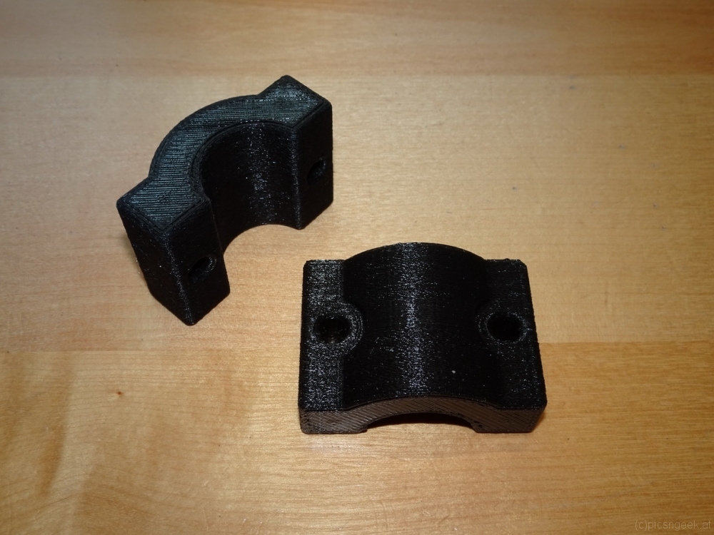
  • 2 supports (3 parts each, 3D printed)
  • 1 NEMA17 stepper motor
  • 1 A4988 stepper motor driver
  • 1 Arduino Nano (Atmel 328 microcontroller)
  • 1 4×20 LCD
  • 1 Joystick module
  • 1 DC-DC converter
  • 2 micro switches with long lever as end switches
  • GT2 10mm timing belt with wire reinforcement
  • 1 GT2 10mm 20 teeth pulley wheel
  • 4 GT2 10mm idler wheels
  • A whole bunch of M3 to M6 screws and nuts
  • 40x3mm flat aluminium
  • 30x50x3mm L-shaped aluminium
  • carbon fiber tubes

The project was really a fun to make. Even more, the resulting slider provides flexibility and transportability! I may configure the slider in any length, depending on the available tubes. The tubes I use, are 37cm in length and have aluminium screw-in adapters to fit one to the other. I have a bag, which I used as personal item in air travel. The bag holds the complete setup for up to 5 meters (exkluding tripods). The bag weighs in at approximately 5kg – so it is a light weight setup for the length possible.

Motorized camera slider

For quite some time I would like to create night time movies in hyperlapses. For me, the most stunning results may be created by moving the camera along a linear path by the use of motorized sliders. Motorized sliders, which are more than 2 meters long, have an impressive price tag. Further more, these tools are bulky and heavy, especially when the setup attached to weighs in a few kilos.
Therefore I decided to build my own with a few goals in mind:

  • light weight
  • portable
  • variable length
  • suitable for a load of a few kilos
  • wider range of speeds
  • extendable for rotation axis
  • direct control for camera(s)

To achieve all or most of these goals, I came up with a design built around carbon fiber tubes with aluminum screw-in fixtures. Appropriate tubes may be built from scratch or are readily available for camera gimbals. I chose the camera gimbal extensions, as there is no big price difference to buying stock material. Further more, they come in a handy size of +/- 40cm in length.
The end supports will have to hold the tubes as well as a gear belt, along which the slider cart will be driven. For long setups, I created supports, to prevent bending and excessive stress to the tubes. Both types of support will have legs as well as tripod mount screw holes (3/8 UNC thread)
The slider cart consists of 4 blocks holding 3 pulley wheels each. The blocks are attached to a base plate (in test setup a plywood sheet). In the middle of the base plate lies the motor unit consisting of a steper motor and 4 guiding wheels to create enough tension for the gear belt to be driven by the motor.

All in all, the shopping list is really limited, as most parts were 3D-printed. What I had to purchase or use (most parts were already to be found in the workshop) was:

  • carbon fiber rods (at least 8)
  • 24 ball bearings type 626 2RS (6x19x6 mm)
  • GT2x10mm belt matching the desired length
  • GT2 20 tooth drive gear
  • 4 guide wheels without teeth for 10mm belt
  • 1 NEMA 14 stepper motor, <3V nominal voltage
  • several M5 and M6 screws, washers and nuts
  • 3/8 UNC thread taper
  • approximately 0.5m of 40x3mm Aluminum sheet
  • 25cm of 30x50x3mm Aluminum L shaped profile
  • Arduino, Stepper motor controller like A4988, 12-18V (lithium) battery
  • 1 can of rubber spray like Plasti-Dip (c)

Most of the time I spent was in CAD constructing the parts. Printing took about 3 days. The pulley wheels have to be sanded for a smooth surface before coating with rubber. The remaining time was spent in cutting, drilling and tapering the aluminum parts, before all parts could be attached together.

The first test run was more than pleasing. See for yourself:

The next thing to do is to create a control box with all the features implemented for every day use 🙂

This site uses cookies. By continuing to use the site (including navigation and scrolling), you agree to the use of cookies. more information

The cookie settings on this website are set to "allow cookies" to give you the best browsing experience possible. If you continue to use this website without changing your cookie settings or you click "Accept" below then you are consenting to this.

Close